441
Parameter Areas Section 9-22
3. Local Network Table of PLC #3:
Relay Network Table
This table lists the network address and node number of the first relay node to
contact in order to reach the destination network. The destination network is
reached through these relay nodes.
Local Network Table
This table lists the network address and unit number of the Communications
Unit connected to the local PLC.
These are settings for the CPU Bus Units which are controlled by the CPU
Unit. The actual settings depend on the model of CPU Bus Unit being used;
refer to the Unit’s Operation Manual for details.
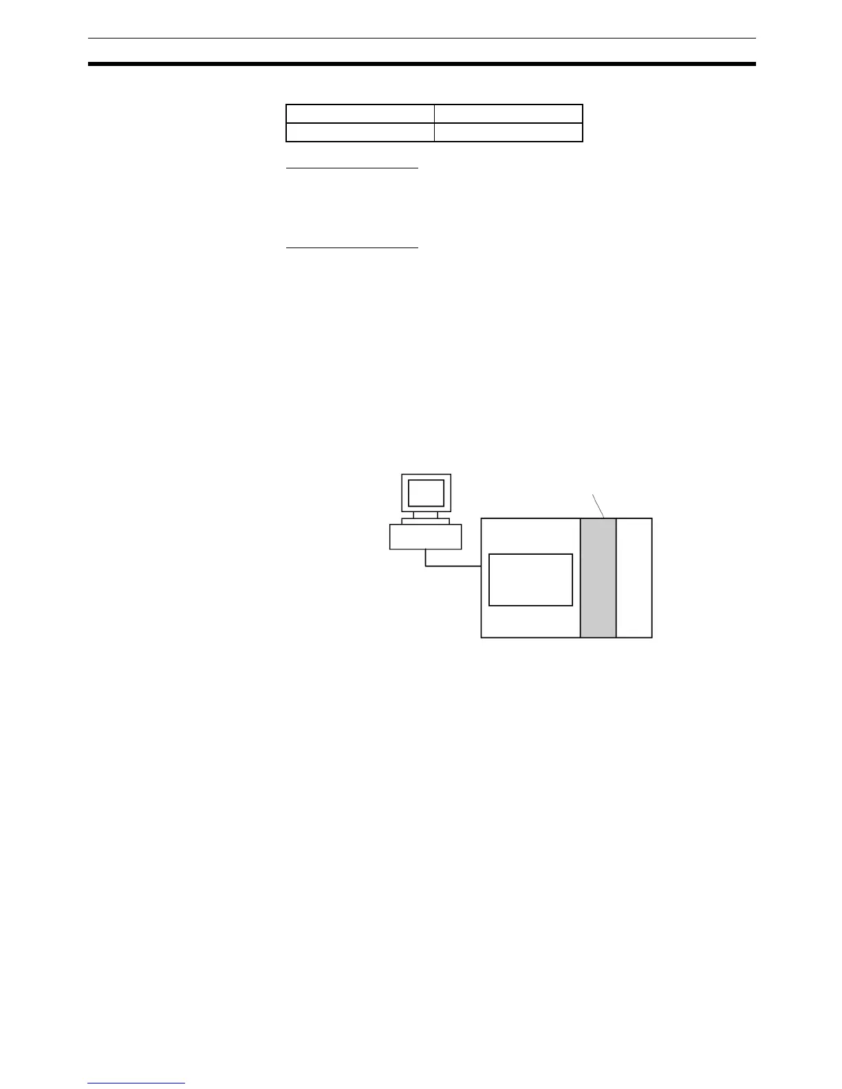
9-22-4 CPU Bus Unit Setting
These settings are not managed directly like the I/O memory’s data areas, but
are set from a Programming Device (CX-Programmer or Programming Con-
sole) like the Registered I/O Table. Refer to the Programming Device’s opera-
tion manual for details on changing these settings.
Local network Unit number
3n
Programming Device
CPU Unit
CPU Bus Unit
CPU Bus Unit
Settings
 Loading...


