315
PLC Setup Section 7-1
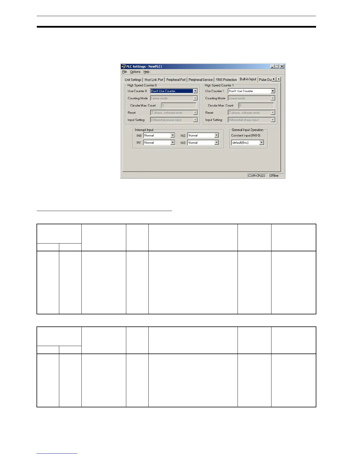
7-1-2-11 Built-in Inputs
The following tables show the CX-Programmer's settings. These settings are
for CJ1M CPU Units equipped with the built-in I/O functions.
Note In the CX-Programmer version 3.1 or lower, the Tab Page's name is Built-in
I/O Settings.
High-speed Counter 0 Operation Settings
High-speed Counter 0 Enable/Disable
High-speed Counter 0 Pulse Input Setting (Pulse Input Mode)
Programming
Console
address
Settings Default Function Related
Auxiliary
Area flags/
bits
Time when
setting is read
by CPU Unit
Word Bits
+50 12 to 15 0 hex: Don’t Use
Counter.
1 hex*:
Use Counter
(60 kHz).
2 hex*:
Use Counter
(100 kHz).
0 hex Specifies whether or not high-speed
counter 0 is being used.
Note When high-speed counter 0 is
enabled (setting 1 or 2), the
input operation settings for
IN8 and IN9 are disabled. The
input operation setting for IN3
is also disabled if the reset
method is set to Phase-Z sig-
nal + software reset.
--- When power is
turned ON
Programming
Console
address
Settings Default Function Related
Auxiliary
Area flags/
bits
Time when
setting is read
by CPU Unit
Word Bits
+50 00 to 03 0 hex: Differential
phase inputs
1 hex: Pulse +
direction inputs
2 hex: Up/Down
inputs
3 hex: Increment
pulse input
0 hex Specifies the pulse-input method for
high-speed counter 0.
--- When power is
turned ON
 Loading...


