348
I/O Allocations Section 8-1
Example
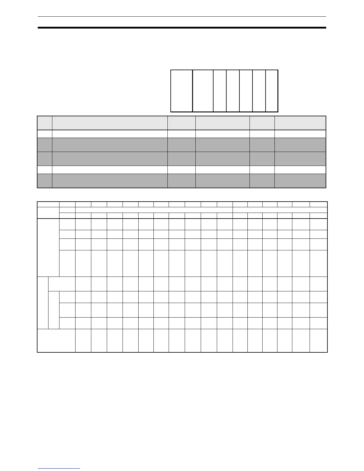
The following example shows the I/O word allocation to Basic I/O Units, Spe-
cial I/O Units, and CPU Bus Units in the CPU Rack.
Data Area Allocations for Built-in I/O (CJ1M CPU Units Only)
Note PWM(891) output1 cannot be used on the CJ1M-CPU21.
Power Supply Unit
CPU Unit
IN
16 pt
CIO
0000
Special
I/O
Unit
CIO
2000
to
2009
CPU
Bus
Unit
CIO
1500
to
1524
OUT
16 pt
CIO
0001
CPU
Bus
Unit
CIO
1525t
o
1549
10234
Slot Unit Words
required
Words allocated Unit
number
Group
0 CJ1W-ID211 16-point DC Input Unit 1 CIO 0000 --- Basic I/O Unit
1 CJ1W-AD081 Analog Input Unit 10 CIO 2000 to
CIO 2009
0 Special I/O Unit
2 CJ1W-SCU41 Serial Communications Unit 25 CIO 1500 to
CIO 1524
0 CPU Bus Unit
3 CJ1W-OD211 16-point Transistor Output Unit 1 CIO 0001 --- Basic I/O Unit
4 CJ1W-CLK21 Controller Link Unit 25 CIO 1525 to
CIO 1549
1 CPU Bus Unit
I/O Code IN0 IN1 IN2 IN3 IN4 IN5 IN6 IN7 IN8 IN9 OUT0 OUT1 OUT2 OUT3 OUT4 OUT5
Address CIO 2960 CIO 2961
Bit00010203040506 07 08 0900010203 04 05
Inputs General-
purpose
inputs
General-
purpose
input 0
General-
purpose
input 1
General-
purpose
input 2
General-
purpose
input 3
General-
purpose
input 4
General-
purpose
input 5
General-
purpose
input 6
General-
purpose
input 7
General-
purpose
input 8
General-
purpose
input 9
--- --- --- --- --- ---
Interrupt
inputs
Interrupt
input 0
Interrupt
input 1
Interrupt
input 2
Interrupt
input 3
--- --- --- --- --- --- --- --- --- --- --- ---
Quick-
response
inputs
Quick-
response
input 0
Quick-
response
input 1
Quick-
response
input 2
Quick-
response
input 3
--- --- --- --- --- --- --- --- --- --- --- ---
High-
speed
counters
--- --- High-
speed
counter
1
(phase-
Z/reset)
High-
speed
counter
0
(phase-
Z/reset)
--- --- High-
speed
counter 1
(phase-
A, incre-
ment, or
count
input)
High-
speed
counter 1
(phase-
B, decre-
ment, or
direction
input)
High-
speed
counter 0
(phase-
A, incre-
ment, or
count
input)
High-
speed
counter 0
(phase-
B, decre-
ment, or
direction
input)
--- --- --- --- --- ---
Out-
puts
General-purpose
outputs
--- --- --- --- --- --- --- --- --- --- Gen-
eral-pur-
pose
output 0
Gen-
eral-pur-
pose
output 1
Gen-
eral-pur-
pose
output 2
Gen-
eral-pur-
pose
output 3
General-
purpose
output 4
General-
purpose
output 5
Pulse
out-
puts
CW/CC
W out-
puts
--- --- --- --- --- --- --- --- --- --- Pulse
output 0
(CW)
Pulse
output 0
(CCW)
Pulse
output 1
(CW)
Pulse
output 1
(CCW)
--- ---
Pulse +
direction
outputs
--- --- --- --- --- --- --- --- --- --- Pulse
output 0
(pulse)
Pulse
output 1
(pulse)
Pulse
output 0
(direc-
tion)
Pulse
output 1
(direc-
tion)
--- ---
Variable
duty ratio
outputs
--- --- --- --- --- --- --- --- --- --- --- --- --- --- PWM(891)
output 0
PWM(891)
output 1
(See note)
Origin search Origin
search 0
(Origin
Input
Signal)
Origin
search 0
(Origin
Proxim-
ity Input
Signal)
Origin
search 1
(Origin
Input
Signal)
Origin
search 1
(Origin
Proxim-
ity Input
Signal)
Origin
search 0
(Posi-
tioning
Com-
pleted
Signal)
Origin
search 1
(Posi-
tioning
Com-
pleted
Signal)
--- --- --- --- --- --- --- --- Origin
search 0
(Error
Counter
Reset
Output)
Origin
search 1
(Error
Counter
Reset
Output)
 Loading...


