656
Connecting to the RS-232C Port on the CPU Unit Appendix F
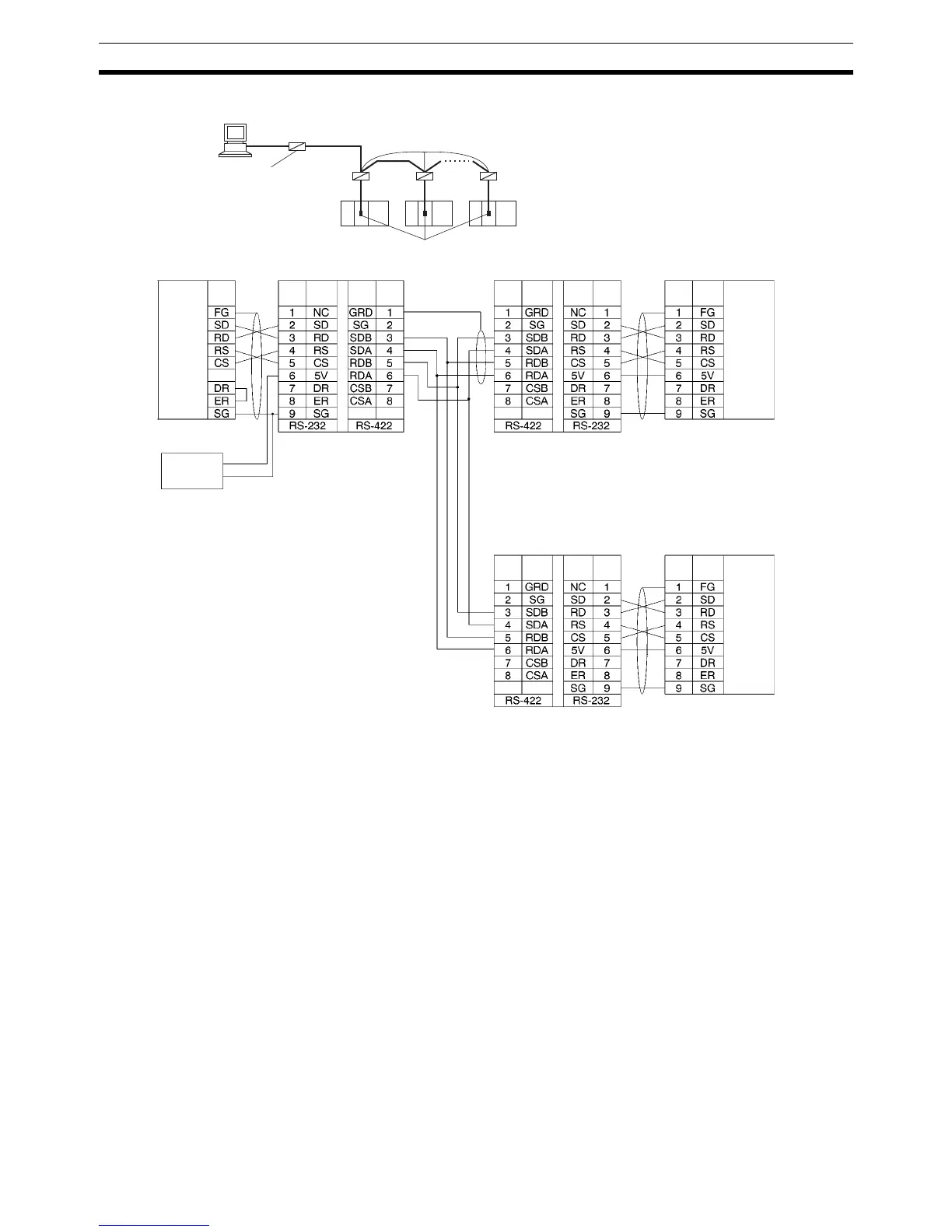
1:N Connections via RS-232C Port
Note 1. We recommend using the following NT-AL001 Link Adapter Connecting Cables to connect to NT-
AL001-E Link Adapters.
XW2Z-070T-1: 0.7 m
XW2Z-200T-1: 2 m
The recommended cables should be wired as shown below. Each signal wire should be twisted with
the SG (signal ground) wire and placed in a shielded cable to prevent the effects of noise in noise-
prone environments. The 5-V wires can also be twisted with the SG wire to increase noise immunity.
RS-232C
RS-422A
RS-232C
RS-232C
5-V (+)
Shield
CPU Unit
(See note 2.)
Personal Computer
Signal
name
Signal
name
Signal
name
Signal
name
Signal
name
Signal
name
Signal
name
Signal
name
Signal
name
RS-232C
Interface
NT-AL001 Link Adapter
D-sub, 9-pin
connector (male)
power (–)
DIP Switch Settings
Pin 1: ON
Pin 2: ON
(terminating resistance)
Pin 3: OFF
Pin 4: OFF
Pin 5: OFF
Pin 6: OFF
DIP Switch Settings
Pin 1: ON
Pin 2: OFF
Pin 3: OFF
Pin 4: OFF
Pin 5: OFF
Pin 6: ON
D-sub, 9-pin connector
(male)
RS-232C
Interface
RS-232C
Interface
(See
note 1.)
(See
note
2.)
(See
note 1.)
(See
note
2.)
D-sub, 9-pin connector
(male)
Communications Board/Unit NT-AL001 Link Adapter
DIP Switch Settings
Pin 1: ON
Pin 2: ON
(terminating resistance)
Pin 3: OFF
Pin 4: OFF
Pin 5: OFF
Pin 6: ON
NT-AL001 Link Adapter
Pin
No.
Pin
No.
Pin
No.
Pin
No.
Pin
No.
Pin
No.
Pin
No.
Pin
No.
NT-AL001
RS-422A/485
RS-232C
RS-232C RS-232C RS-232C
NT-AL001
terminating
resistance ON, 5-V
power required
Terminating resistance ON
RS-232C ports
 Loading...


