123
C-mode Command Details Section 4-3
Response Format
Note “SP” represents a space (20 Hex).
Parameters Program Address (Command)
Designates the program address in four digits decimal (BCD) for beginning
the search for the specified timer/counter.
Timer/Counter Type (Command)
Designate in ASCII characters the timer/counter instruction type for reading
the constant SV or the word address in which it is stored.
Timer/Counter Number (Command)
Designate in four digits (BCD) the timer/counter instruction number for read-
ing the constant SV or the word address in which it is stored. (Data register
designation is not possible.)
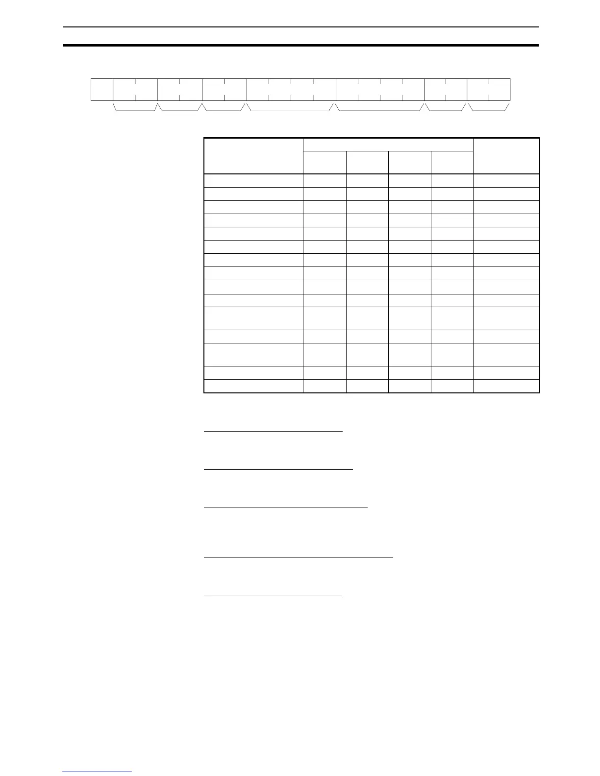
Constant/Area Classification (Response)
The constant or I/O memory area classification is returned, in ASCII, to this
parameter.
SV/Word Address (Response)
The constant SV or the word address in which it is stored is returned to this
parameter.
Limitations Timers T2048 to T4095 and counters C2048 to C4095 cannot be read.
The SV of the first timer/counter found after the designated program address
will be read.
If the SV is outside of range for the timer/counter type or number, an end code
of 16 (command not supported) will be returned.
Classification Constant/area classification SV or word
address
Charac-
ter 1
Charac-
ter 2
Charac-
ter 3
Charac-
ter 4
Constant C O N (SP) 0000 to 9999
CIO C I O (SP) 0000 to 6143
AR A R (SP) (SP) 0000 to 0959
HR H R (SP) (SP) 0000 to 0511
WR W R (SP) (SP) 0000 to 0511
Timer T I M (SP) 0000 to 2047
Counter C N T (SP) 0000 to 2047
DM D M (SP) (SP) 0000 to 9999
DM (indirect) D M
*
(SP) 0000 to 9999
EM current bank E M (SP) (SP) 0000 to 9999
EM (indirect) current
bank
EM
*
(SP) 0000 to 9999
EM banks 0 to C E M 0 to C (SP) 0000 to 9999
EM (indirect) banks 0 to
C
E M 0 to C
*
0000 to 9999
Data register D R (SP) (SP) 0000 to 0015
Index register (indirect) , I R (SP) 0000 to 0015
x 16
0
@R$
OP1 OP2 OP3
OP4
x 10
0
x 10
0
x 10
1
x 16
1
x 10
3
x 10
2
x 10
1
↵*
Unit No. (BCD)
Header
code
End code Constant/area
classification
SV/word address
TerminatorFCS
 Loading...


