79
CPM1/CPM1A Interrupt Functions Section 1-6
Count Range The CPM1/CPM1A’s high-speed counter uses linear operation and the count
(present value) is stored in SR 248 and SR 249. (The upper four digits are
stored in SR 249 and the lower four digits are stored in SR 248.)
An overflow will occur if the count exceeds the upper limit in the count range
and an underflow will occur if the count goes below the lower limit in the count
range.
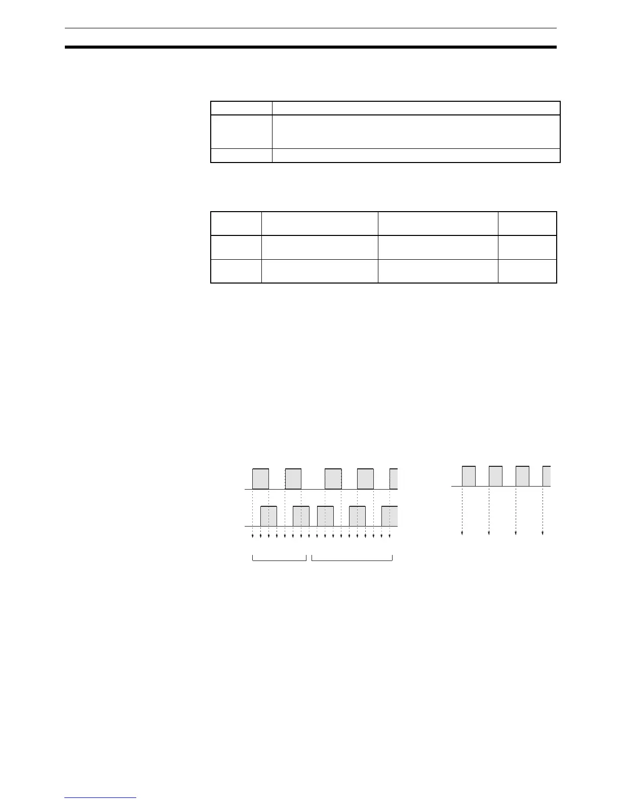
Processing Two types of signals can be input from a pulse encoder. The count mode used
for the high-speed counter will depend on the signal type. The count mode
and reset mode are set in DM 6642; these settings become effective when the
power is turned on or PC operation is started.
Up/Down Mode:
A phase-difference 4
× two-phase signal (A-phase and B-phase) and a Z-
phase signal are used for inputs. The count is incremented or decrement-
ed according to differences in the 2-phase signals.
Incrementing Mode:
One single-phase pulse signal and a count reset signal are used for inputs.
The count is incremented according to the single-phase signal.
Note One of the reset methods described below should always be used to reset the
counter when restarting it. The counter will be automatically reset when pro-
gram execution is started or stopped.
The following signal transitions are handled as forward (incrementing) pulses:
A-phase leading edge to B-phase leading edge to A-phase trailing edge to B-
phase trailing edge. The following signal transitions are handled as reverse
(decrementing) pulses: B-phase leading edge to A-phase leading edge to B-
phase trailing edge to A-phase trailing edge.
The Up/Down Mode always uses a 4
× phase-difference input. The number of
counts for each encoder revolution would be 4 times the resolution of the
counter. Select the encoder based on the countable ranges.
Mode Count range
Up/Down F003 2767 to 0003 2767 (–32,767 to 32,767)
The leftmost digit in SR 248 indicates the sign. F is negative, 0 is
positive.
Incrementing 0000 0000 to 0006 5535 (0 to 65,535)
Error Incrementing Up/Down Present
value
Overflow Occurs when the count is
incremented from 65,535.
Occurs when the count is
incremented from 32,767.
0FFF FFFF
Underflow --- Occurs when the count is
decremented from –32,767.
FFFF FFFF
1234567876543210–1–2
1 2 3 4
A-phase
B-phase
Up/Down Mode
Count
Incremented Decremented
Count
Pulse input
Incrementing Mode
Incremented only