210
Step Instructions Section 5-14
5-14 Step Instructions:
STEP DEFINE and STEP START–STEP(08)/SNXT(09)
Limitations All control bits must be in the same word and must be consecutive.
Description The step instructions STEP(08) and SNXT(09) are used together to set up
breakpoints between sections in a large program so that the sections can be
executed as units and reset upon completion. A section of program will usu-
ally be defined to correspond to an actual process in the application. (Refer to
the application examples later in this section.) A step is like a normal program-
ming code, except that certain instructions (i.e., END(01), IL(02)/ILC(03),
JMP(04)/JME(05), and SBN(92)) may not be included.
STEP(08) uses a control bit in the IR or HR areas to define the beginning of a
section of the program called a step. STEP(08) does not require an execution
condition, i.e., its execution is controlled through the control bit. To start exe-
cution of the step, SNXT(09) is used with the same control bit as used for
STEP(08). If SNXT(09) is executed with an ON execution condition, the step
with the same control bit is executed. If the execution condition is OFF, the
step is not executed. The SNXT(09) instruction must be written into the pro-
gram so that it is executed before the program reaches the step it starts. It can
be used at different locations before the step to control the step according to
two different execution conditions (see example 2, below). Any step in the pro-
gram that has not been started with SNXT(09) will not be executed.
Once SNXT(09) is used in the program, step execution will continue until
STEP(08) is executed without a control bit. STEP(08) without a control bit
must be preceded by SNXT(09) with a dummy control bit. The dummy control
bit may be any unused IR or HR bit. It cannot be a control bit used in a
STEP(08).
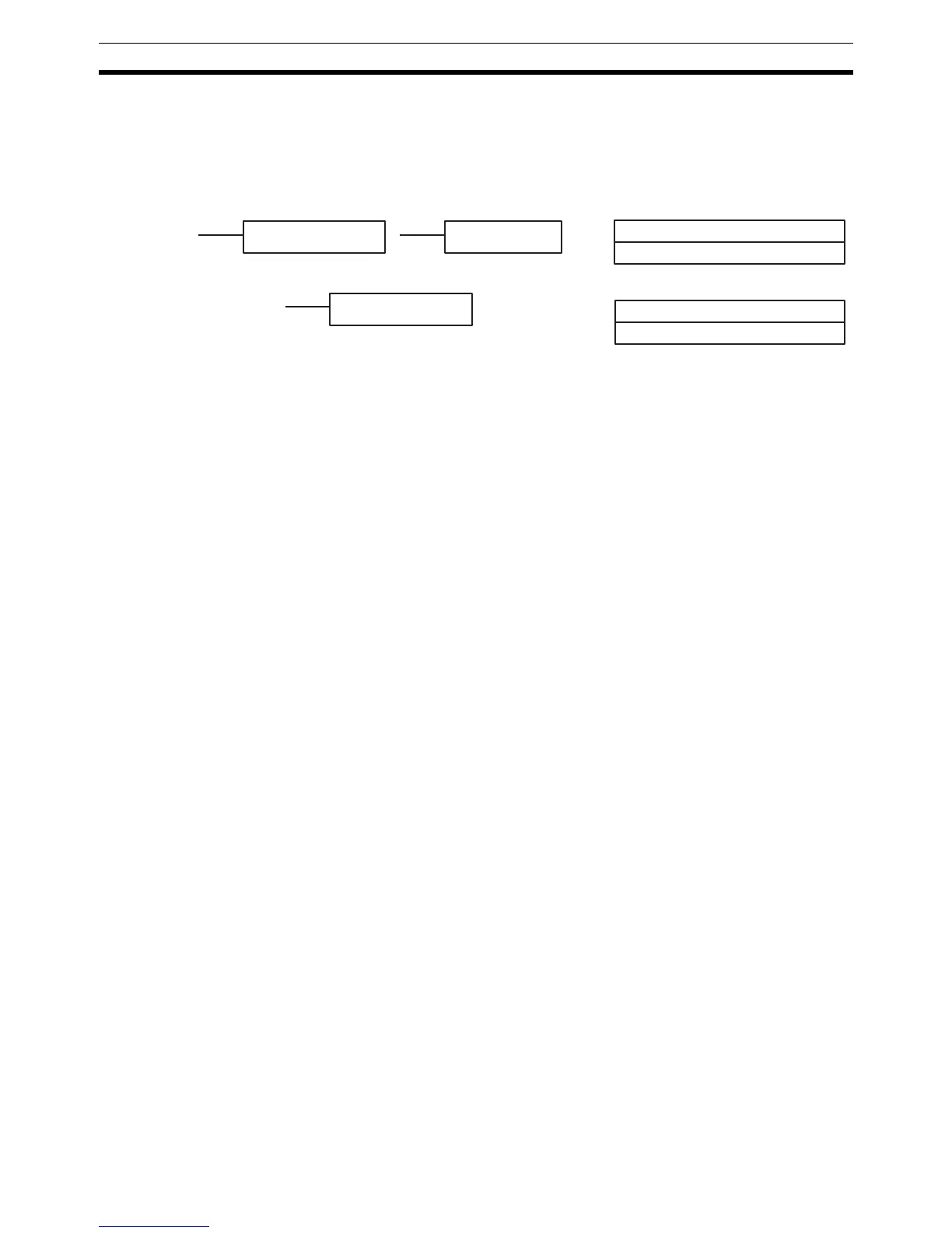
B: Control bit
IR, AR, HR, LR
Ladder Symbols Definer Data Areas
STEP(08) B
STEP(08)
SNXT(09) B
B: Control bit
IR, AR, HR, LR