97
Communications Functions Section 1-9
Example Program This example shows a BASIC program that reads the status of the CPM1’s
inputs in IR 000. For more details, refer to SECTION 6 Host Link Commands.
An FCS (frame check sequence) check isn’t performed on the received
response data in this program. Be sure that the host computer’s RS-232C port
is configured correctly before executing the program.
1010 ’CPM1 SAMPLE PROGRAM
1020 ’SET THE COMMAND DATA
1030 S$=”@00RR00000001”
1040 FCS=0
1050 FOR I=1 TO LEN(S$)
1060 FCS=FCS XOR ASC(MID$(S$,I,1))
1070 NEXT I
1080 FCS$=(FCS):IF LEN(FCS$)=1 THEN FCS$=”0”+FCS$
1090 CLOSE 1
1100 CLS
1110 PRINT ”SENDING COMMAND”
1120 OPEN ”COM:E73” AS #1
1130 PRINT #1,S$ + FCS + CHR$(13);
1140 CLS
1150 PRINT ”RECEIVING RESPONSE DATA”
1160 LINE INPUT #1,A$
1170 PRINT A$
1180 END
1-9-5 SRM1 Host Link Communications
Host link communications were developed by OMRON for the purpose of con-
necting PCs and one or more host computers by RS-232C cable, and control-
ling PC communications from a host computer. Normally the host computer
issues a command to a PC, and the PC automatically sends back a response.
Thus the communications are carried out without the PCs being actively
involved. The PCs also have the ability to initiate data transmissions when
direct involvement is necessary.
In general, there are two means for implementing host link communications.
One is based on C-mode commands, and the other on FINS (CV-mode) com-
mands. The SRM1 supports C-mode commands only. For details on host link
communications, refer to SECTION 6 Host Link Commands.
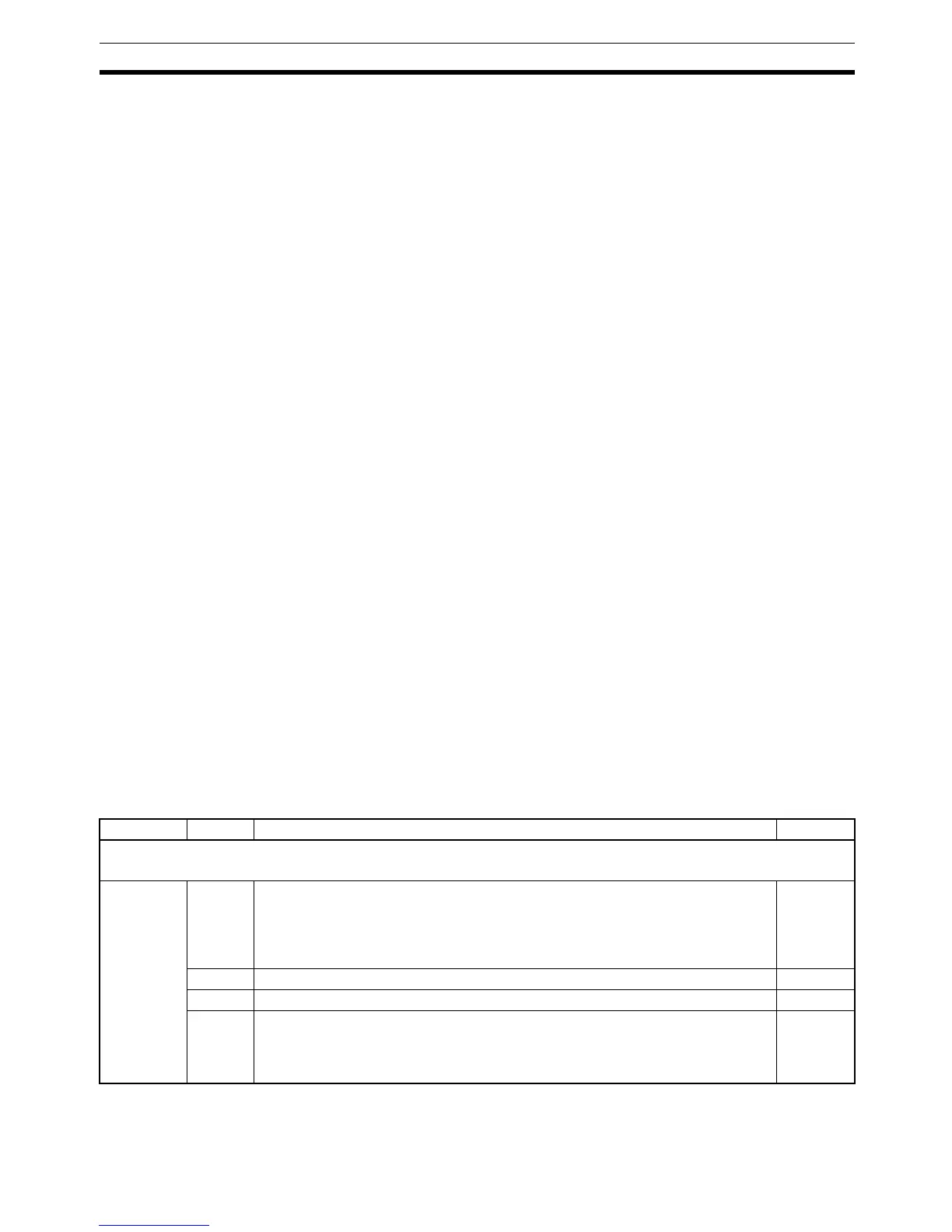
PC Setup Settings The SRM1’s peripheral port and RS-232C port settings must be set properly
in order to use the host link communications, as shown in the following table.
Word Bit Function Setting
Peripheral Port Settings
The following settings are effective after transfer to the PC.
DM 6650 00 to 03 Port settings
0: Standard (1 start bit, 7-bit data, even parity, 2 stop bits, 9,600 bps)
1: Settings in DM 6651
(Other settings will cause a non-fatal error, the default setting (0) will be used, and
AR 1302 will turn ON.)
To match
host
parame-
ters
04 to 07 Not used. 0
08 to 11 Not used. 0
12 to 15 Communications mode
0: Host link; 1: No protocol
(Other settings will cause a non-fatal error, the default setting (0) will be used, and
AR 1302 will turn ON.)
0: Host link
 Loading...


