234
Shift Instructions Section 5-16
Description When the execution condition is OFF, SRD(75) is not executed. When the
execution condition is ON, SRD(75) shifts data between St and E (inclusive)
by one digit (four bits) to the right. 0 is written into the leftmost digit of St and
the rightmost digit of E is lost.
Precautions If a power failure occurs during a shift operation across more than 50 words,
the shift operation might not be completed.
A 0 will be shifted into the most significant digit of St every cycle if the undiffer-
entiated form of SRD(75) is used. Use the differentiated form (@SRD(75)) or
combine SRD(75) with DIFU(13) or DIFD(14) to shift just one time.
Flags ER: The St and E words are in different areas, or St is less than E.
Indirectly addressed DM word is non-existent. (Content of *DM word
is not BCD, or the DM area boundary has been exceeded.)
5-16-9 REVERSIBLE SHIFT REGISTER – SFTR(84)
Limitations St and E must be in the same data area and St must be less than or equal
to E.
DM 6144 to DM 6655 cannot be used for C, St, or E.
Description SFTR(84) is used to create a single- or multiple-word shift register that can
shift data to either the right or the left. To create a single-word register, desig-
nate the same word for St and E. The control word provides the shift direction,
the status to be put into the register, the shift pulse, and the reset input. The
control word is allocated as follows:
The data in the shift register will be shifted one bit in the direction indicated by
bit 12, shifting one bit out to CY and the status of bit 13 into the other end
whenever SFTR(84) is executed with an ON execution condition as long as
2
St
3 1
E
4 5 C8F
Lost data
0
...
C: Control word
IR, SR, AR, DM, HR, LR
St: Starting word
IR, SR, AR, DM, HR, LR
Ladder Symbols
Operand Data Areas
E: End word
IR, SR, AR, DM, HR, LR
SFTR(84)
C
St
E
@SFTR(84)
C
St
E
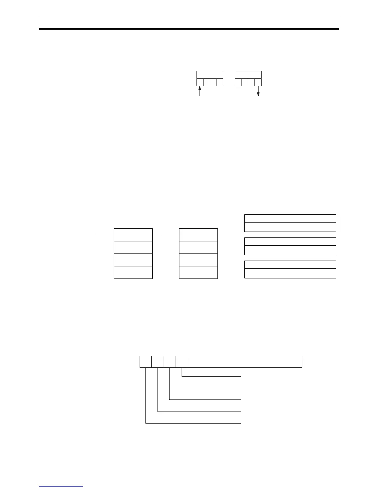
15 14 13 12 Not used.
Shift direction
1 (ON): Left (LSB to MSB)
0 (OFF): Right (MSB to LSB)
Status to input into register
Shift pulse bit
Reset