347
Special Instructions Section 5-26
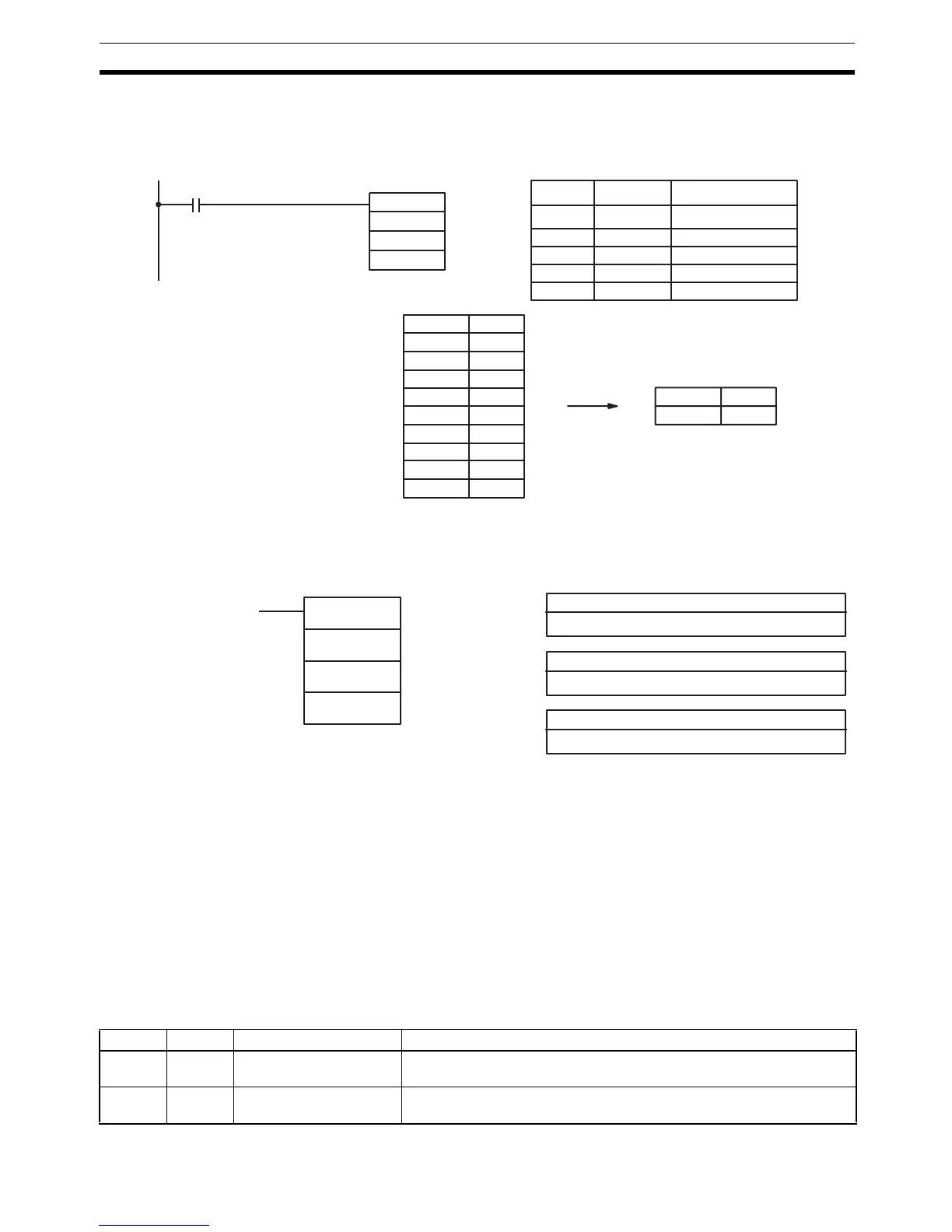
Example In the following example, the 10 word range from DM 0010 to DM 0019 is
searched for addresses that contain the same data as DM 0000 (#FFFF).
Since DM 0012 contains the same data, the EQ Flag (SR 25506) is turned
ON and #0012 is written to DM 0001.
5-26-15PID CONTROL – PID(––)
Limitations This instruction is available in the CQM1-CPU4@-E/-EV1 only.
DM 6144 to DM 6655 cannot be used for IW, P1 to P1+32, or OW.
P1 to P1+32 must be in the same data area.
!Caution A total of 33 continuous words starting with P1 must be provided for PID(––)
to operate correctly. Also, PID(––) may not operate dependably in any of the
following situations: In interrupt programs, in subroutines, between IL(02) and
ILC(03), between JMP(04) and JME(05), and in step programming
(STEP(08)/SNXT(09)). Do not program PID(––) in these situations.
Description PID(––) performs PID control based on the parameters specified in P1
through P1+6. The data in IW is used to calculate the output data that is writ-
ten to OW. The following table shows the function of the parameter words.
@SRCH(––)
DM 0010
#0010
00001
DM 0000
Address Instruction Operands
00000 LD 00001
00001 @SRCH(––)
# 0010
DM 0010
DM 0000
DM 0010 0000
DM 0011 9898
DM 0012 FFFF
DM 0013 9797
DM 0014 AAAA
DM 0015 9595
DM 0016 1414
DM 0017 0000
DM 0018 0000
DM 0019 FFFF
DM 0000 FFFF
DM 0001 0012
IW: Input data word
IR, SR, AR, DM, HR, LR
Ladder Symbol Operand Data Areas
OW: Output data word
IR, SR, AR, DM, HR, LR
P1: First parameter word
IR, SR, DM, HR, LR
PID(––)
IW
P1
OW
Word Bits Parameter name Function/Setting range
P1 00 to 15 Set value (SV). This is the target value for PID control. It can be set to any binary num-
ber with the number of bits set by the input range parameter.
P1+1 00 to 15 Proportional band width. This parameter specifies the proportional band width/input range ratio
from 0.1% to 999.9%. It must be BCD from 0001 to 9999.