334
Special Instructions Section 5-26
CY: ON when the time between the execution of FPD(––) and the execu-
tion of a diagnostic output exceeds T.
5-26-8 INTERRUPT CONTROL – INT(89)
Note This instruction is not supported by SRM1 PCs.
Limitations DM 6644 to DM 6655 cannot be used for D when CC=002.
Description When the execution condition is OFF, INT(89) is not executed. When the exe-
cution condition is ON, INT(89) is used to control interrupts and performs one
of the six functions shown in the following table depending on the value of CC.
Note Refer to 1-5 CQM1 Interrupt Functions and 1-6 CPM1/CPM1A Interrupt Func-
tions for more details.
These six functions are described in more detail below. Refer to page 22 for
more information on these functions.
Mask/Unmask I/O
Interrupts (CC=000)
This function is used to mask and unmask I/O interrupt inputs 00000 to 00003
(00003 to 00006 in CPM1/CPM1A PCs). Masked inputs are recorded, but
ignored. When an input is masked, the interrupt program for it will be run as
soon as the bit is unmasked (unless it is cleared beforehand by executing
INT(89) with CC=001).
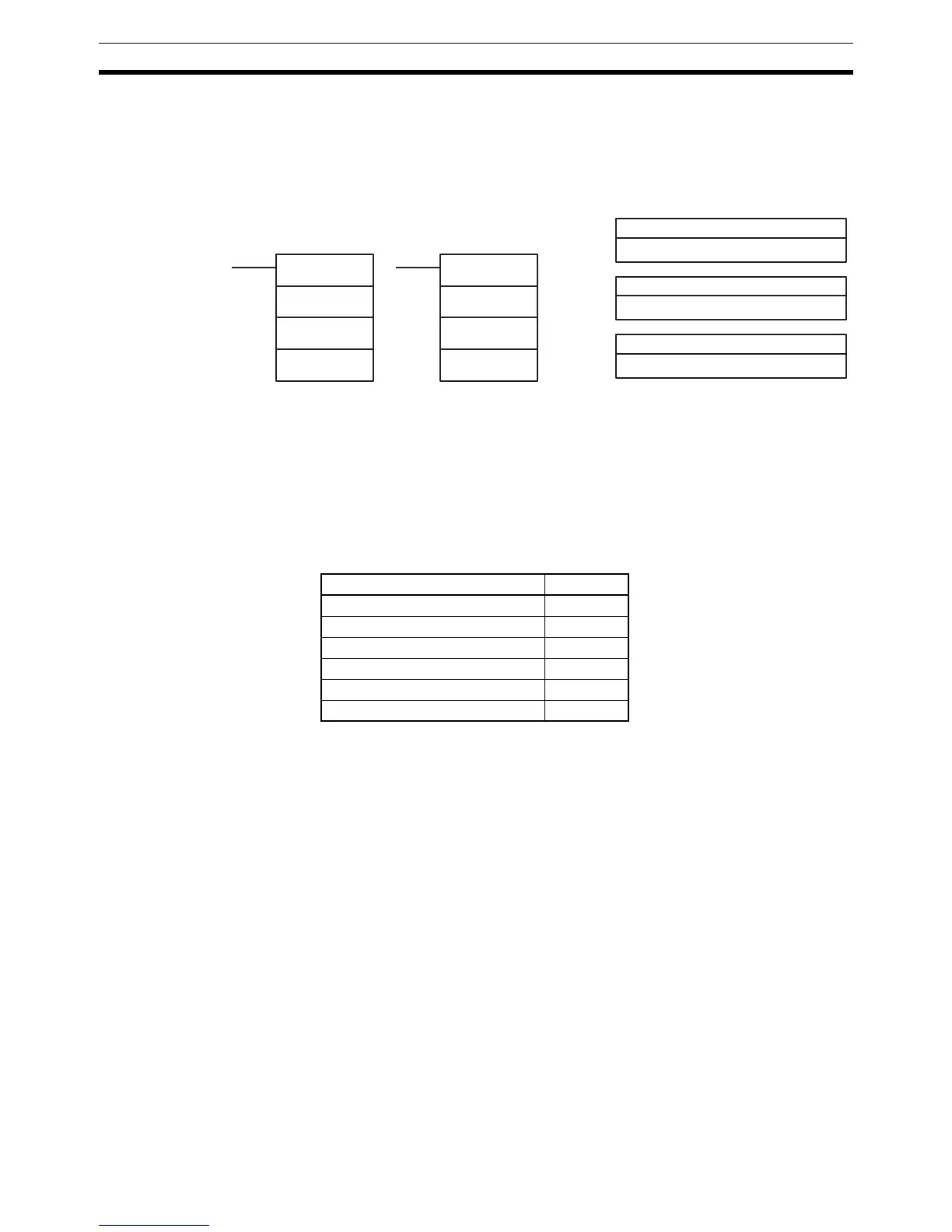
Ladder Symbols
INT(89)
CC
000
D
@INT(89)
CC
000
D
CC: Control code
# (000 to 003, 100, or 200)
000: No function
# (000)
Operand Data Areas
D: Control data
IR, SR, AR, DM, HR, TC, LR, TR, #
INT(89) function CC
Mask/unmask input interrupts 000
Clear input interrupts 001
Read current mask status 002
Renew counter SV 003
Mask all interrupts 100
Unmask all interrupts 200