124
Advanced I/O Instructions (CQM1 Only) Section 2-2
The hexadecimal key information that is input to IR 000 by HKY(––) is con-
verted to hexadecimal and stored in words DM1000 and DM1001.
IR 00015 is used as an “ENTER key,” and when IR 00015 turns ON, the num-
bers stored in DM 1000 and DM 1001 are transferred to DM 0000 and DM
0001.
2-2-3 DIGITAL SWITCH INPUT – DSW(87)
With this instruction, 4-digit or 8-digit BCD set values are read from a digital
switch. DSW(87) utilizes 5 output bits and either 4 input bits (for 4 digits) or 8
input bits (for 8 digits).
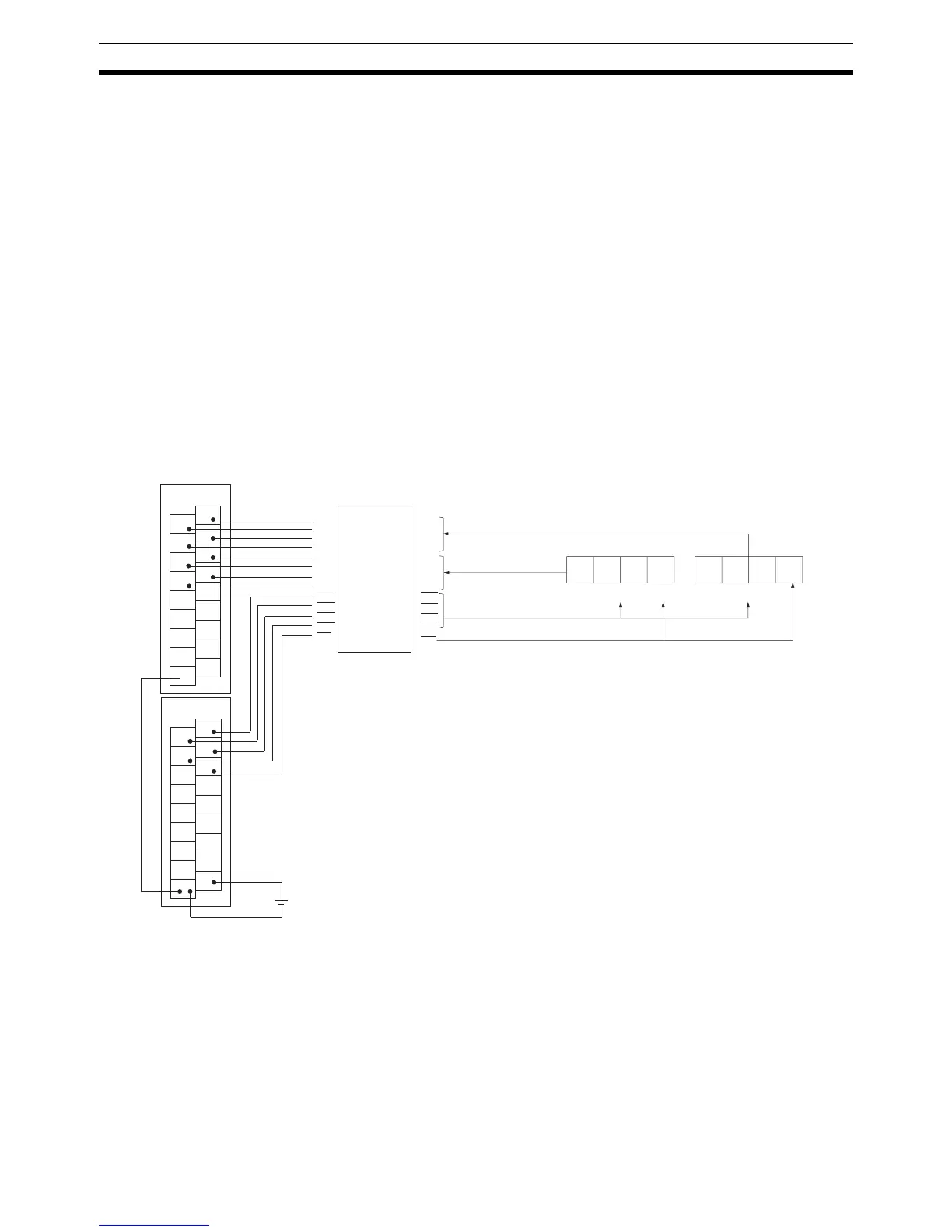
Hardware Connect the digital switch and the Input and Output Units as shown in the dia-
gram below. In the diagram, an 8-digit input is shown. When using a 4-digit
input, connect D0 through D3 from the digital switch to input points 0 through
3. In either case, output point 5 will be turned ON when one round of data is
read, but there is no need to connect output point 5 unless required for the
application.
1
3
5
7
9
11
13
15
COM
0
2
4
6
8
10
12
14
COM
ID212
1
3
5
7
9
11
13
15
COM
0
2
4
6
8
10
12
14
COM
OD212
D
0
D
1
D
2
D
3
D
0
D
1
D
2
D
3
D
0
D
1
D
2
D
3
D
0
D
1
D
2
D
3
CS
0
CS
1
CS
2
CS
3
Interface
A7E data line
leftmost digits
To A7E chip selection
To A7E RD terminal
Leftmost digits A7E
Rightmost digits
A7E data line rightmost digits
Input Unit
Output Unit
Note An interface to convert signals from 5 V to 24 V is
required to connect an A7E digital switch.
CS
0
RD
CS
1
CS
2
CS
3
RD