216
Timer and Counter Instructions Section 5-15
5-15-3 REVERSIBLE COUNTER – CNTR(12)
Limitations Each TC number can be used as the definer in only one TIMER or COUNTER
instruction. TC numbers run from 000 through 511 in the CQM1 PCs and from
000 through 127 in the CPM1/CPM1A/SRM1 PCs.
Description The CNTR(12) is a reversible, up/down circular counter, i.e., it is used to count
between zero and SV according to changes in two execution conditions, those
in the increment input (II) and those in the decrement input (DI).
The present value (PV) will be incremented by one whenever CNTR(12) is
executed with an ON execution condition for II and the last execution condition
for II was OFF. The present value (PV) will be decremented by one whenever
CNTR(12) is executed with an ON execution condition for DI and the last exe-
cution condition for DI was OFF. If OFF to ON changes have occurred in both
II and DI since the last execution, the PV will not be changed.
If the execution conditions have not changed or have changed from ON to
OFF for both II and DI, the PV of CNT will not be changed.
When decremented from 0000, the present value is set to SV and the Com-
pletion Flag is turned ON until the PV is decremented again. When incre-
mented past the SV, the PV is set to 0000 and the Completion Flag is turned
ON until the PV is incremented again.
CNTR(12) is reset with a reset input, R. When R goes from OFF to ON, the
PV is reset to zero. The PV will not be incremented or decremented while R is
ON. Counting will begin again when R goes OFF. The PV for CNTR(12) will
not be reset in interlocked program sections or by the effects of power inter-
ruptions.
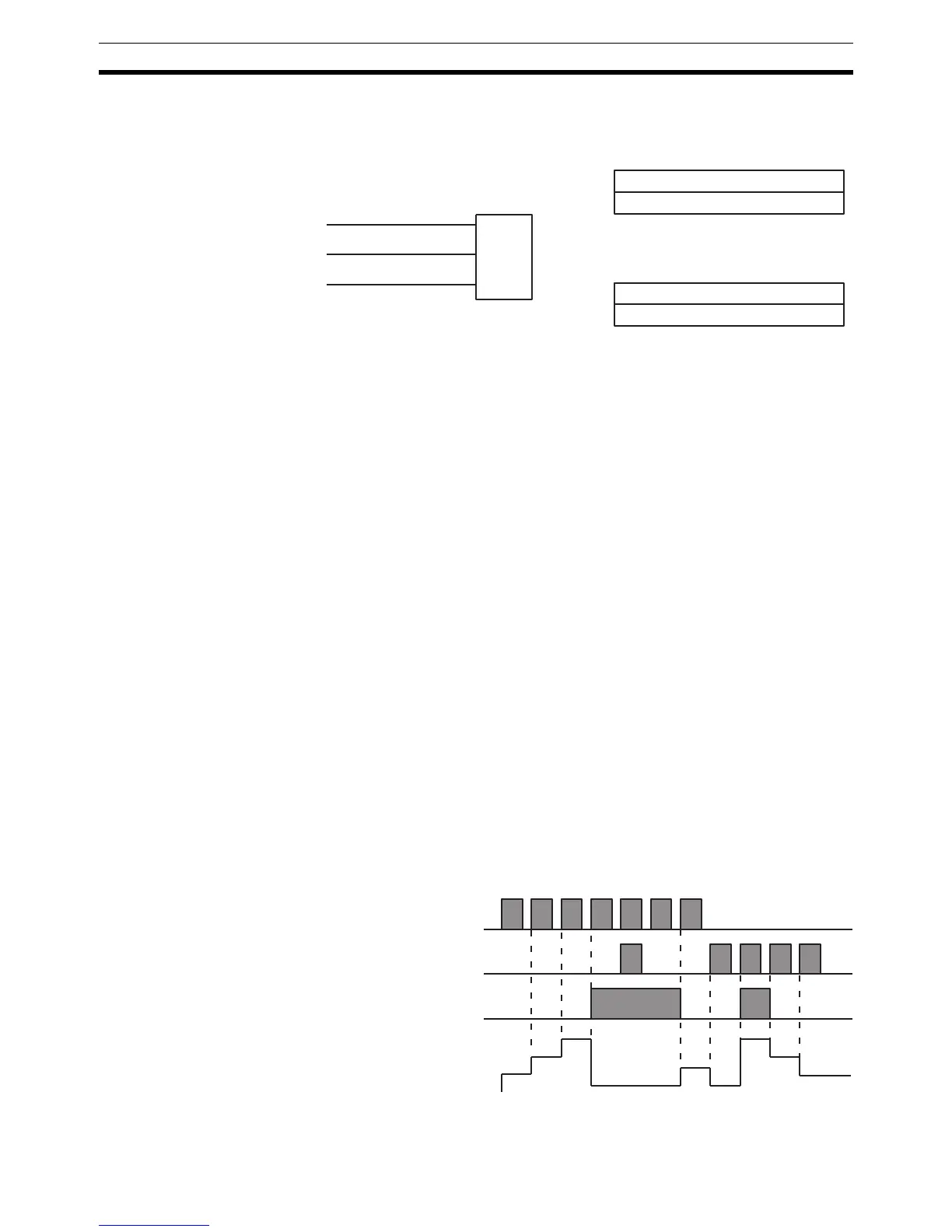
Changes in II and DI execution conditions, the Completion Flag, and the PV
are illustrated below starting from part way through CNTR(12) operation (i.e.,
when reset, counting begins from zero). PV line height is meant to indicate
changes in the PV only.
N: TC number
#
Ladder Symbol
Definer Values
SV: Set value (word, BCD)
IR, SR, AR, DM, HR, LR, #
Operand Data Areas
II
DI
R
CNTR(12)
N
SV
Execution condition
on increment (II)
Execution condition
on decrement (DI)
ON
OFF
ON
OFF
Completion Flag
ON
OFF
PV
SV
SV – 1
SV – 2
0001
0000
0000
SV
SV – 1
SV – 2