325
Special Instructions Section 5-26
if the delay is positive). The negative delay cannot be such that the required
data was executed before sampling was started.
5-26-2 MESSAGE DISPLAY – MSG(46)
Limitations DM 6649 to DM 6655 cannot be used for FM.
Description When executed with an ON execution condition, MSG(46) reads eight words
of extended ASCII code from FM to FM+7 and displays the message on the
Programming Console. The displayed message can be up to 16 characters
long, i.e., each ASCII character code requires eight bits (two digits). Refer to
Appendix H for the ASCII codes. Japanese katakana characters are included
in this code.
If not all eight words are required for the message, it can be stopped at any
point by inputting “OD.” When OD is encountered in a message, no more
words will be read and the words that normally would be used for the mes-
sage can be used for other purposes.
Message Buffering and
Priority
Up to three messages can be buffered in memory. Once stored in the buffer,
they are displayed on a first in, first out basis. Since it is possible that more
than three MSG(46)s may be executed within a single cycle, there is a priority
scheme, based on the area where the messages are stored, for the selection
of those messages to be buffered.
The priority of the data areas is as follows for message display:
LR > IR > HR > AR > TC > DM
In handling messages from the same area, those with the lowest ad-
dress values have higher priority.
In handling indirectly addressed messages (i.e. *DM), those with the
lowest final DM addresses have higher priority.
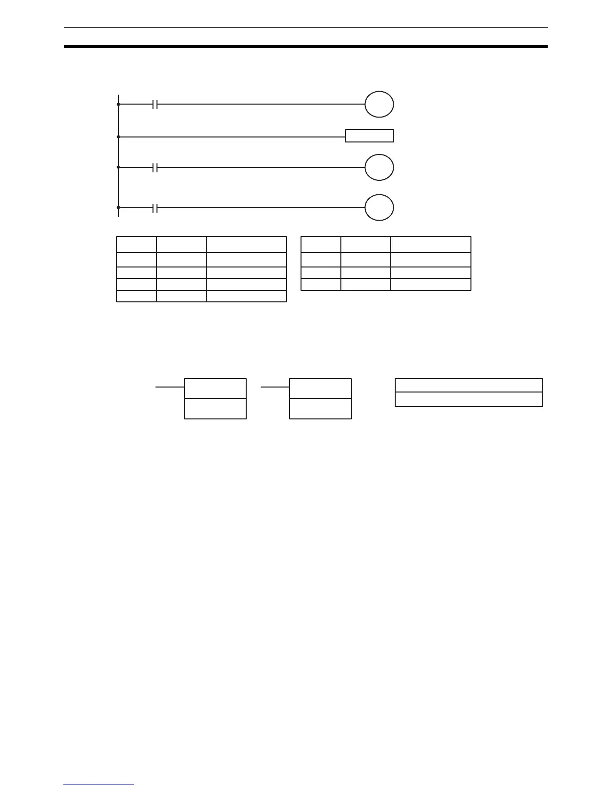
TRSM(45)
00000
AR
2514
AR 2513 ON when tracing
00200
00201
AR 2512 ON when trace is complete
Starts data tracing.
Designates point for
tracing.
Indicates that tracing has
been completed.
Address Instruction Operands Address Instruction Operands
00000 LD 0000
00001 OUT AR 2514
00002 TRSM(45)
00003 LD AR 2513
00004 OUT 00200
00005 LD AR 2512
00006 OUT 00201
Indicates that tracing is in
progress.
FM: First message word
IR, SR, AR, DM, HR, LR
Ladder Symbols Operand Data Areas
MSG(46)
FM
@MSG(46)
FM