133
Quick-response Inputs (CPM1/CPM1A Only) Section 2-6
!Caution The analog setting may change with changing temperatures. Do not use the
analog adjustment controls for applications that require a precise, fixed set-
ting.
CPM1/CPM1A Program Example
The following ladder program uses the CPM1/CPM1A’s analog settings. The
analog setting in SR 250 (0000 to 0200 BCD) is determined by adjusting ana-
log adjustment control 0. This value is used to adjust the timer’s set value from
0.0 to 20.0 seconds.
2-6 Quick-response Inputs (CPM1/CPM1A Only)
The CPM1/CPM1A have quick response inputs that can be used to enable
inputting shorter signals.
All 10-point CPU Units have 2 quick-response input terminals and the 20-,
30-, and 40-point CPU Units have 4 quick-response input terminals. The
same terminals are used for quick-response inputs and interrupt inputs.
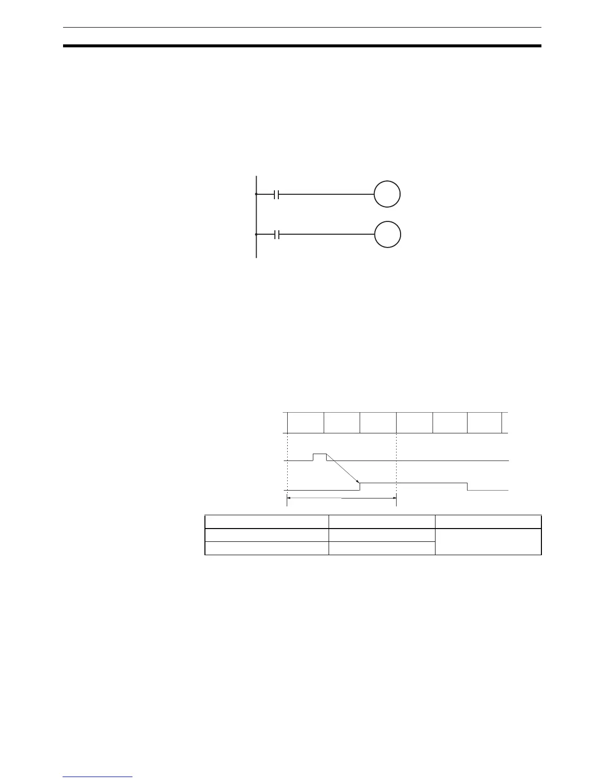
Quick-response Operation Quick-response inputs have an internal buffer, so input signals shorter than
one cycle can be detected. Signals with a pulse width as short as 0.2 ms can
be detected, regardless of their timing during the PC cycle.
Start condition
SR 250 is specified as
the timer's set value.
TIM
000
01003
TIM 000
CPU Unit Input bits Min. input pulse width
10-point CPU Units IR 00003 to IR 00004 0.2 ms
20-, 30-, 40-point CPU Units IR 00003 to IR 00006
Overseeing
processes
Program
execution
I/O
refreshing
Overseeing
processes
Program
execution
I/O
refreshing
Input signal
(00003)
IR 00003
One c
ycle