356
Advanced I/O Instructions Section 5-28
Description When the execution condition is OFF, HKY(––) is not executed. When the exe-
cution condition is ON, HKY(––) inputs data from a hexadecimal keypad con-
nected to the input indicated by IW. The data is input in two ways:
1,2,3... 1. An 8-digit shift register is created in D and D+1. When a key is pressed on
the hexadecimal keypad, the corresponding hexadecimal digit is shifted
into the least significant digit of D. The other digits of D, D+1 are shifted left
and the most significant digit of D+1 is lost.
2. The bits of D+2 and bit 4 of OW indicate key input. When one of the keys
on the keypad (0 to F) is being pressed, the corresponding bit in D+2 (00
to 15) and bit 4 of OW are turned ON.
Note When one of the keypad keys is being pressed, input from the other keys is
disabled.
HKY(––) inputs each digit in 3 to 12 cycles, and then starts over and contin-
ues inputting. Refer to page 122 for more details on HKY(––).
Flags ER: Indirectly addressed DM word is non-existent. (Content of *DM word
is not BCD, or the DM area boundary has been exceeded.)
D and D+2 are not in the same data area.
SR 25408: ON while HKY(––) is being executed.
5-28-4 TEN KEY INPUT – TKY(18)
Limitations This instruction is available in the CQM1 only.
D
1
and D
1
+1 must be in the same data area.
DM 6143 to DM 6655 cannot be used for D
1
.
Description When the execution condition is OFF, TKY(18) is not executed. When the exe-
cution condition is ON, TKY(18) inputs data from a ten-key keypad connected
to the input indicated by IW. The data is input in two ways:
1,2,3... 1. An 8-digit shift register is created in D
1
and D
1
+1. When a key is pressed
on the ten-key keypad, the corresponding BCD digit is shifted into the least
significant digit of D
1
. The other digits of D
1
, D
1
+1 are shifted left and the
most significant digit of D
1
+1 is lost.
2. The first ten bits of D
2
indicate key input. When one of the keys on the key-
pad (0 to 9) is being pressed, the corresponding bit of D
2
(00 to 09) is
turned ON.
Note When one of the keypad keys is being pressed, input from the other keys is
disabled.
TKY(18) can be used in several locations in the program by changing the
input word, IW. Refer to page 120 for more details on TKY(18).
D
1
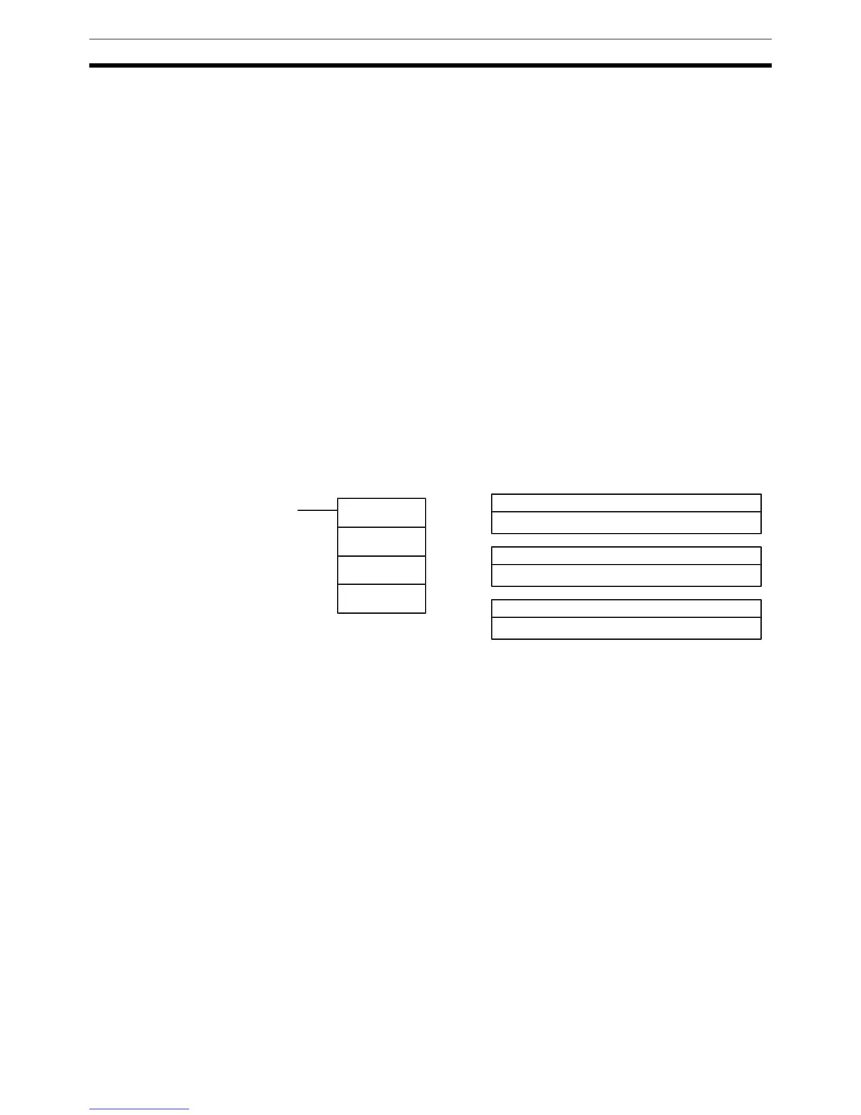
: First register word
IR, SR, AR, DM, HR, TC, LR
IW: Input word
IR, SR, AR, DM, HR, TC, LR
Ladder Symbols Operand Data Areas
TKY(18)
IW
D
1
D
2
D
2
: Key input word
IR, SR, AR, DM, HR, TC, LR

 Loading...


