89
Communications Functions Section 1-9
Note 1. When the maximum number of CompoBus/S nodes is set to 16, IN8 to
IN15 can be used as work bits.
2. CompoBus/S Terminals with less than 8 points are allocated bit addresses
from either 0 or 8.
3. CompoBus/S Terminals with 16 points can be set for only even number ad-
dresses.
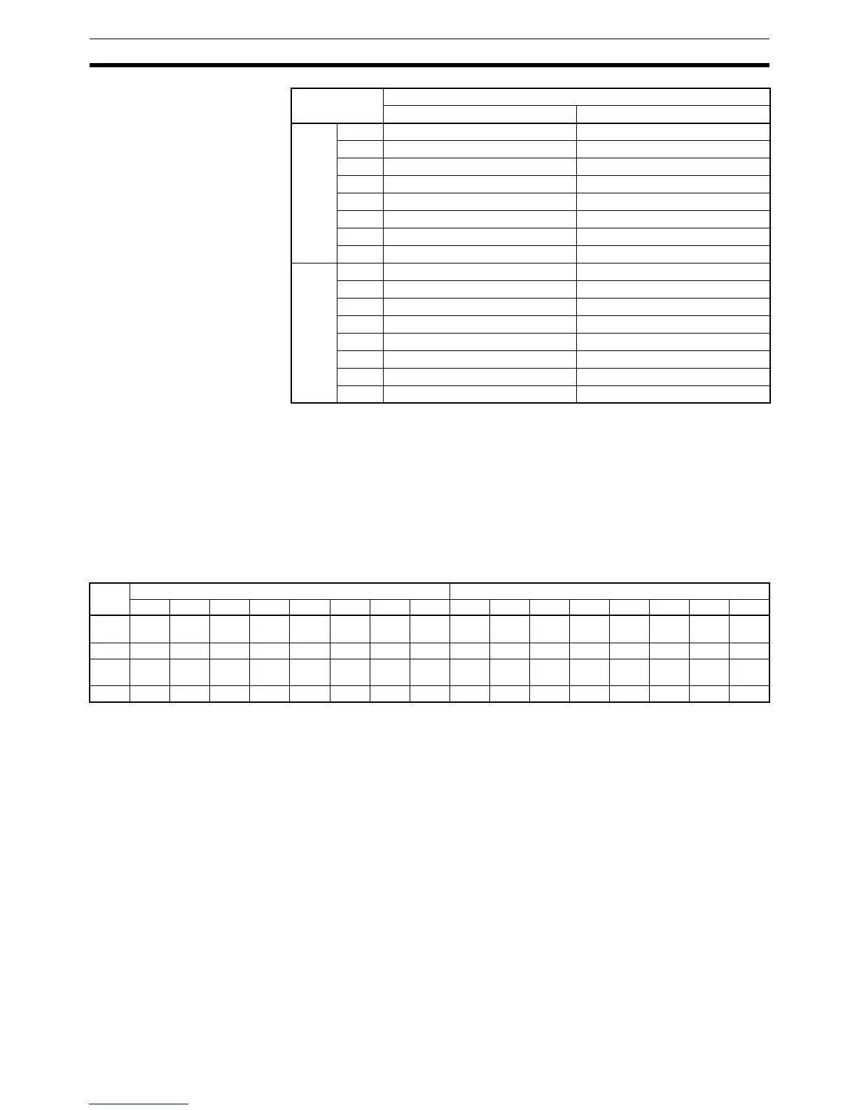
Status Flags The communications status between CompoBus/S terminals is output
through AR04 to AR07 Slave Add Flags and Slave Communications Error
Flags.
Note 1. IN0 to IN15 are the input terminals and OUT0 to OUT15 are the output ter-
minals.
2. When the maximum number of CompoBus/S units is set to 16, IN8 to IN15
and OUT8 to OUT15 cannot be used.
3. The Slave Add Flag turns ON when a slave joins the communications.
When the power to the CPU Unit is turned OFF and ON again all bits will
turn OFF.
4. The Slave Communications Error Flag turns ON when a slave participating
in the network is separated from the network. The bit will turn OFF when
the slave re-enters the network.
1-9 Communications Functions
CQM1 Communications The following types of communications can be executed through the ports of
the CQM1.
• Host link communications with a host computer
• RS-232C communications with a computer or other device
• One-to-one link communications with another CQM1
Word Bit
1514131211109876543210
Input IR 000 IN1 IN0
IR 001 IN3 IN2
IR 002 IN5 IN4
IR 003 IN7 IN6
IR 004 IN9 IN8
IR 005 IN11 IN10
IR 006 IN13 IN12
IR 007 IN15 IN14
Output IR 010 OUT1 OUT0
IR 011 OUT3 OUT2
IR 012 OUT5 OUT4
IR 013 OUT7 OUT6
IR 014 OUT9 OUT8
IR 015 OUT11 OUT10
IR 016 OUT13 OUT12
IR 017 OUT15 OUT14
Word Uppermost bits: Slave Communications Error Flags Lower Bits: Slave Add Flags
1514131211109876543210
AR04 OUT
7
OUT
6
OUT
5
OUT
4
OUT
3
OUT
2
OUT
1
OUT
0
OUT
7
OUT
6
OUT
5
OUT
4
OUT
3
OUT
2
OUT
1
OUT
0
AR05 IN7 IN6 IN5 IN4 IN3 IN2 IN1 IN0 IN7 IN6 IN5 IN4 IN3 IN2 IN1 IN0
AR06 OUT
15
OUT
14
OUT
13
OUT
12
OUT
11
OUT
10
OUT
9
OUT
8
OUT
15
OUT
14
OUT
13
OUT
12
OUT
11
OUT
10
OUT
9
OUT
8
AR07 IN15 IN14 IN13 IN12 IN11 IN10 IN9 IN8 IN15 IN14 IN13 IN12 IN11 IN10 IN9 IN8