269
Conversion Instructions Section 5-19
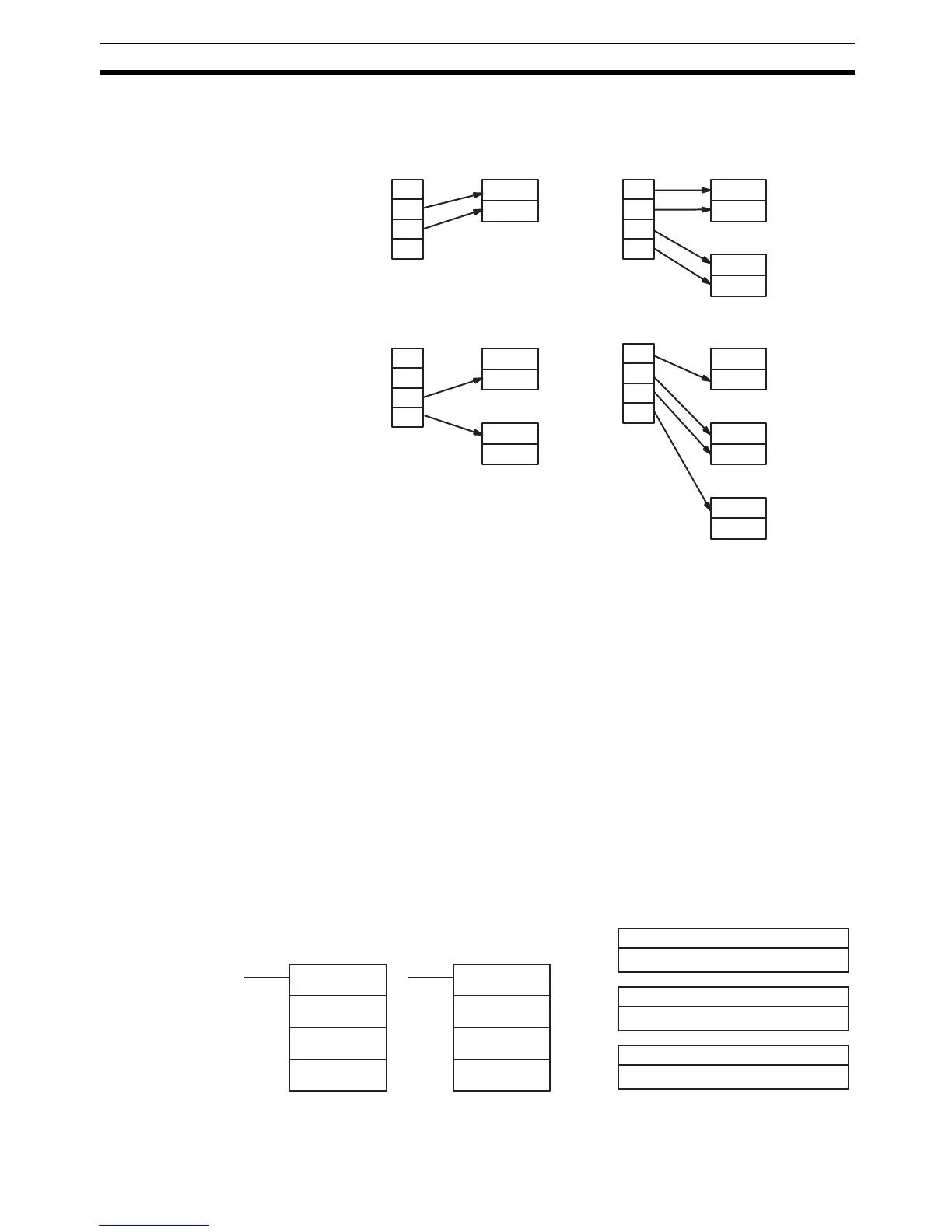
Some examples of Di values and the 4-bit binary to 8-bit ASCII conversions
that they produce are shown below.
Parity The leftmost bit of each ASCII character (2 digits) can be automatically
adjusted for either even or odd parity. If no parity is designated, the leftmost bit
will always be zero.
When even parity is designated, the leftmost bit will be adjusted so that the
total number of ON bits is even, e.g., when adjusted for even parity, ASCII “31”
(00110001) will be “B1” (10110001: parity bit turned ON to create an even
number of ON bits); ASCII “36” (00110110) will be “36” (00110110: parity bit
turned OFF because the number of ON bits is already even). The status of the
parity bit does not affect the meaning of the ASCII code.
When odd parity is designated, the leftmost bit of each ASCII character will be
adjusted so that there is an odd number of ON bits.
Flags ER: Incorrect digit designator, or data area for destination exceeded.
Indirectly addressed DM word is non-existent. (Content of *DM word
is not BCD, or the DM area boundary has been exceeded.)
5-19-9 ASCII-TO-HEXADECIMAL – HEX(––)
Limitations This instruction is available in the CQM1/SRM1 only.
0
1
2
3
S
Di: 0011
D
0
1
2
3
Di: 0030
S
0
1
2
3
Di: 0130
S
Di: 0112
0
1
2
3
S
1st half
2nd half
D
1st half
2nd half
D+1
1st half
2nd half
D
1st half
2nd half
D+1
1st half
2nd half
D
1st half
2nd half
D+1
1st half
2nd half
D+2
1st half
2nd half
S: First source word
IR, SR, AR, DM, HR, TC, LR, #
Di: Digit designator
IR, SR, AR, DM, HR, TC, LR, #
Ladder Symbols
Operand Data Areas
D: Destination word
IR, SR, AR, DM, HR, LR
HEX(––)
S
Di
D
@HEX(––)
S
Di
D