349
Communications Instructions Section 5-27
The cycle time is more than twice as long as the sampling period, so
PID(––) cannot be executed accurately. PID(––) will be executed in
this case.
Indirectly addressed DM word is non-existent. (Content of *DM word
is not BCD, or the DM area boundary has been exceeded.)
CY: ON when PID processing has been performed. (OFF when the sam-
pling period has not elapsed.)
5-27 Communications Instructions
5-27-1 RECEIVE – RXD(47)
Limitations This instruction is available in the CQM1/SRM1 only.
D and D+(N÷2)–1 must be in the same data area.
DM 6144 to DM 6655 cannot be used for D or N.
N must be BCD from #0000 to #0256. (#0000 to #0061 in host link mode)
Description When the execution condition is OFF, RXD(47) is not executed. When the
execution condition is ON, RXD(47) reads N bytes of data received at the port
specified in the control word, and then writes that data in words D to
D+(N
÷2)–1. Up to 256 bytes of data can be read at one time.
If fewer than N bytes are received, the amount received will be read.
Note Refer to 1-9 Communications Functions for details on using the RXD(47)
instruction, setting communications protocol in the PC Setup, etc.
!Caution The CQM1 or SRM1 will be incapable of receiving more data once 256 bytes
have been received if received data is not read using RXD(47). Read data as
soon as possible after the Reception Completed Flag is turned ON (AR 0806
for the RS-232C port, AR 0814 for the peripheral port.)
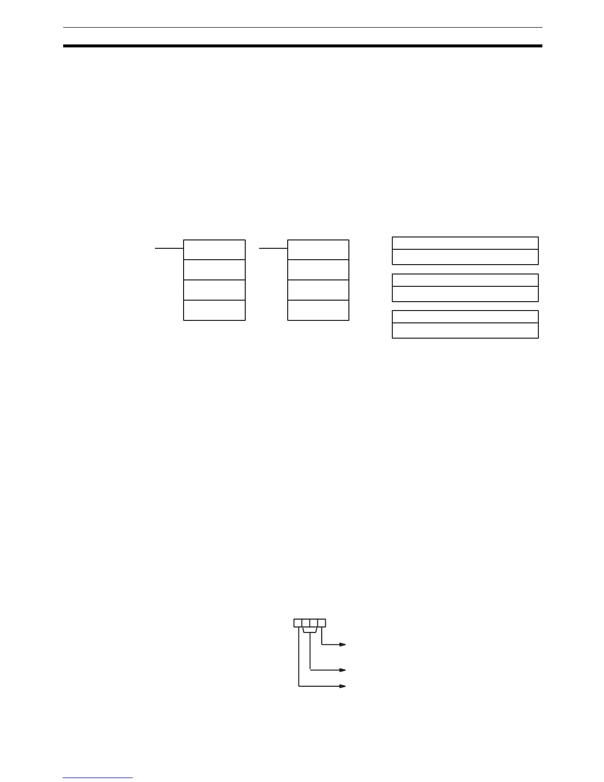
Control Word The value of the control word determines the port from which data will be read
and the order in which data will be written to memory.
D: First destination word
IR, SR, AR, DM, HR, TC, LR
C: Control word
#
Ladder Symbols
Operand Data Areas
N: Number of bytes
IR, SR, AR, DM, HR, TC, LR, #
RXD(47)
D
C
N
@RXD(47)
D
C
N
Byte order 0: Most significant bytes first
1: Least significant bytes firs