355
Advanced I/O Instructions Section 5-28
5-28-2 DIGITAL SWITCH INPUT – DSW(87)
Limitations This instruction is available in the CQM1 only.
DM 6144 to DM 6655 cannot be used for R.
Description DSW(87) is used to read the value set on a digital switch connected to I/O
Units. When the execution condition is OFF, DSW(87) is not executed. When
the execution condition is ON, DSW(87) reads the value (either 4 or 8-digit)
set on the digital switch from IW and places the result in R.
If the value is an 8-digit number, it is placed in R and R+1, with the most signif-
icant digits placed in R+1. The number of digits is set in DM 6639 of the PC
Setup.
DSW(87) reads the 4 or 8-digit data in 12 cycles, and then starts over and
continues reading the data.
Refer to page 124 for more information on DSW(87) and its applications.
Flags ER: IW and/or OW are not allocated to the correct I/O Units.
Indirectly addressed DM word is non-existent. (Content of *DM word
is not BCD, or the DM area boundary has been exceeded.)
R and R+1 are not in the same data area. (When the CQM1 is set to
receive 8-digit data.)
SR 25410: ON while DSW(87) is being executed.
5-28-3 HEXADECIMAL KEY INPUT – HKY(––)
Limitations This instruction is available in the CQM1 only.
D and D+2 must be in the same data area.
Do not use HKY(––) more than twice in the program.
DM 6144 to DM 6655 cannot be used for D.
IW: Input word
IR, SR, AR, DM, HR, TC, LR
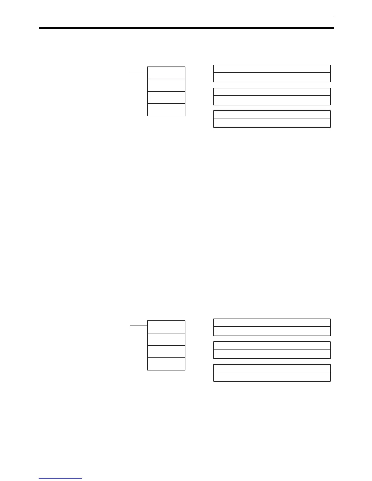
Ladder Symbols Operand Data Areas
DSW(87)
IW
OW
R
R: First result word
IR, SR, AR, DM, HR, TC, LR
OW: Output word
IR, SR, AR, DM, HR, TC, LR
OW: Control signal output word
IR, SR, AR, DM, HR, TC, LR
IW: Input word
IR, SR, AR, DM, HR, TC, LR
Ladder Symbols Operand Data Areas
HKY(––)
IW
OW
D
D: First register word
IR, SR, AR, DM, HR, TC, LR