336
Special Instructions Section 5-26
ing bit in D to 1 in order to renew the input’s counter SV. (Bits 00 to 03 corre-
spond to 00000 to 00003 in CQM1 PCs, 00003 to 00006 in CPM1/CPM1A
PCs.)
Mask/Unmasking All
Interrupts (CC=100/200)
This function is used to mask or unmask all interrupt processing. Masked
inputs are recorded, but ignored. Refer to page 44 for details.
The control data, D, is not used for this function. Set D to #0000.
Flags ER: A counter’s SV is incorrect. (CC=003 only)
Indirectly addressed DM word is non-existent. (Content of *DM word
is not BCD, or the DM area boundary has been exceeded.)
CC=100 or 200 while an interrupt program was being executed.
CC=100 when all inputs were already masked.
CC=200 when all inputs were already unmasked.
CC and/or D are not within specified values.
5-26-9 SET PULSES – PULS(65)
Limitations This instruction is available in the CPM1A with transistor outputs and
CQM1 only.
N and N+1 must be in the same data area.
DM 6143 to DM 6655 cannot be used for N.
Description PULS(65) is used to set parameters for pulse outputs that are started later in
the program using SPED(64) or ACC(––). The parameters that can be set are
the number of pulses that will be output in independent mode, the direction of
pulse outputs from ports 1 and 2, and the deceleration point for pulse outputs
controlled by ACC(––) mode 0.
Since PULS(65) has a relatively long execution time, the cycle time can be
reduced by executing the differentiated version (@PULS(65)) of this instruc-
tion only when it is needed.
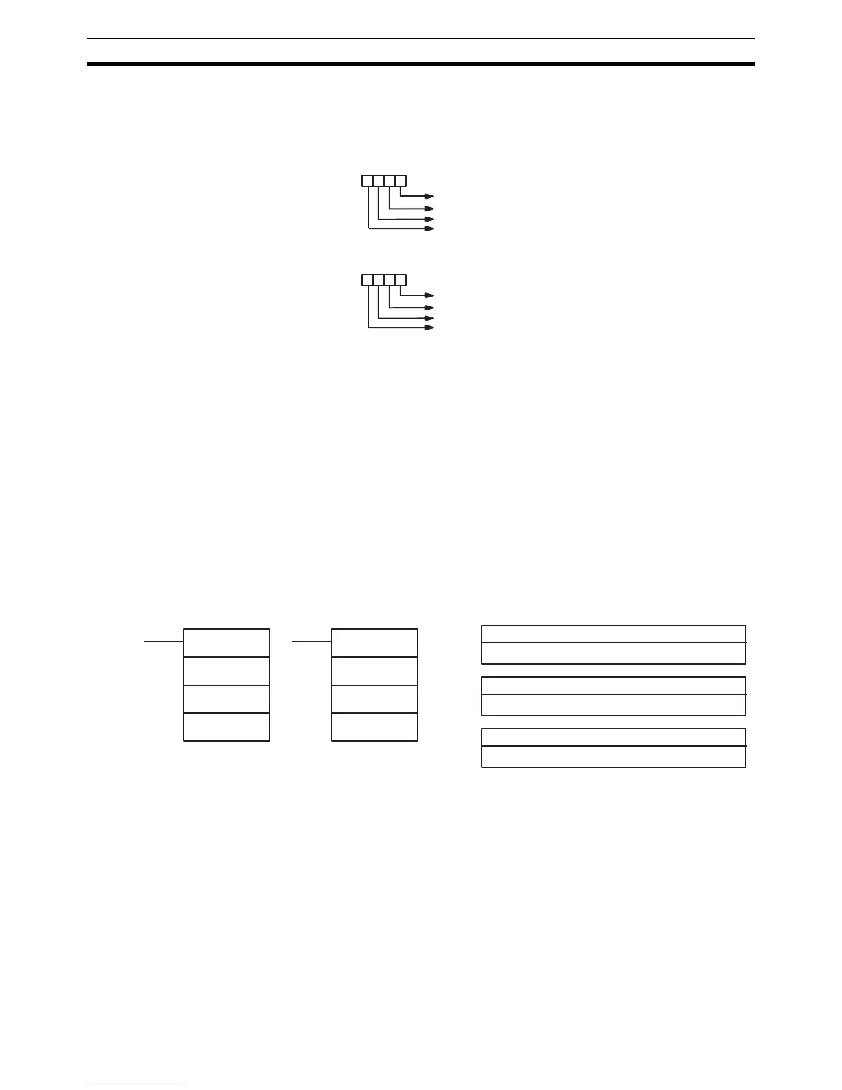
Interrupt input 00000 counter SV (0: Change, 1: Don't change)
Interrupt input 00001 counter SV (0: Change, 1: Don't change)
Interrupt input 00002 counter SV (0: Change, 1: Don't change)
Interrupt input 00003 counter SV (0: Change, 1: Don't change)
Word D bits: 3 2 1 0
CQM1 PCs
CPM1/CPM1A PCs
Interrupt input 00003 counter SV (0: Change, 1: Don't change)
Interrupt input 00004 counter SV (0: Change, 1: Don't change)
Interrupt input 00005 counter SV (0: Change, 1: Don't change)
Interrupt input 00006 counter SV (0: Change, 1: Don't change)
Word D bits: 3 2 1 0
P: Port specifier
000, 001, or 002
Ladder Symbols Operand Data Areas
@PULS(65)
P
C
N
N: Number of pulses
IR, SR, AR, DM, HR, LR
C: Control data
000 to 005
PULS(65)
P
C
N

 Loading...


