337
Special Instructions Section 5-26
Note Refer to 1-3 Pulse Output Function (CQM1 Only) for more details.
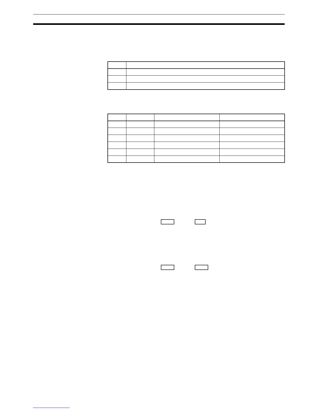
Port Specifier (P) The port specifier indicates the pulse output location. The parameters set by
the in C and N will apply to the next SPED(64) or ACC(––) instruction in which
the same port output location is specified.
Control Data (C) The control data determines the direction of the pulse output to ports 1 and 2
and indicates whether the number of pulses and/or the deceleration point are
specified in N to N+3. This operand should be set to 000 when P=000.
The direction setting is valid until program execution is stopped or PULS(65)
is executed again.
Number of Pulses and
Deceleration Point
When C=000 to 003, N+1, N contains the 8-digit number of pulses setting for
independent mode pulse outputs. N+1, N can be from 00000001 to
16777215. The pulse output started by SPED(64) or ACC(––) will stop auto-
matically when this number of pulses has been output.
When C=002 or 003, N+3, N+2 contains the 8-digit number of pulses setting
for the deceleration point used in ACC(––) mode 0. N+3, N+2 can be from
00000001 to 16777215. The pulse output started by ACC(––) will begin decel-
eration when this number of pulses have been output.
When C=004 or 005, neither the number of pulses nor the deceleration point
are set. Set N=000 when C=004 or 005.
Frequency Changes The number of pulses set to be output will be used even if SPED(64) is used
to change the pulse frequency during operation.
For example, if the number of pulses setting is 2,100 and the frequency is
changed from 1 KHz to 100 Hz, pulse output will stop in:
12 s if the pulse frequency is changed after 1 s at 1 KHz.
3 s if the pulse frequency is changed after 2 s at 1 KHz.
Flags ER: There is an error in the instruction settings.
If a data area boundary is exceeded.
Indirectly addressed DM word is non-existent. (Content of *DM word
is not BCD, or the DM area boundary has been exceeded.)
PULS(65) is executed in an interrupt subroutine while a pulse I/O or
high-speed counter instruction is being executed in the main program.
P Pulse output location
000 Output bit
001 Port 1
002 Port 2
C Direction Number of pulses Deceleration point
000 CW Set in N and N+1 Not set.
001 CCW Set in N and N+1 Not set.
002 CW Set in N and N+1 Set in N+2 and N+3
003 CCW Set in N and N+1 Set in N+2 and N+3
004 CW Not set. Not set.
005 CCW Not set. Not set.
Leftmost 4 digits Rightmost 4 digits
N+1 N Number of pulses:
Possible range
0000 0001 to 1677 7215
Leftmost 4 digits Rightmost 4 digits
N+3 N+2 Deceleration point:
Possible range
0000 0001 to 1677 7215