348
Special Instructions Section 5-26
When the execution condition is OFF, PID(––) is not executed and the instruc-
tion’s data is maintained. While the execution condition is OFF, the desired
output data can be written directly to OW for manual control.
When the execution condition first goes from OFF to ON, PID(––) reads the
parameters and initializes the work area. There is a built-in function to change
the output data continuously at startup because sudden changes in the output
data might adversely affect the controlled system.
!Caution Changes made to the parameters will not be effective until the execution con-
dition for PID(––) goes from OFF to ON.
Note Do not use PID(––) in the following situations; it may not be executed properly.
In interrupt programs
In subroutine programs
In interlocked program sections (between IL and ILC)
In jump program sections (between JMP and JME)
In step ladder program section (created with STEP)
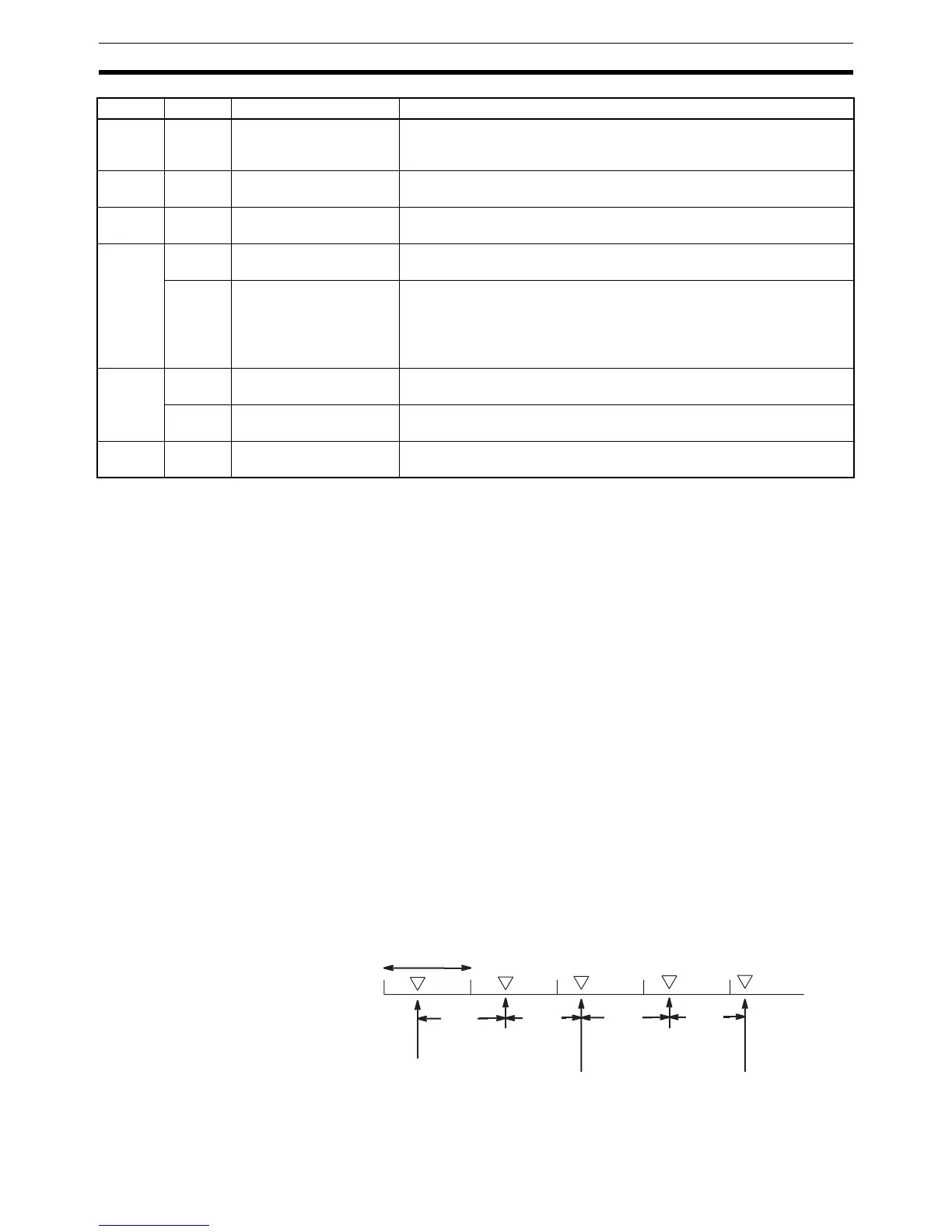
When the execution condition is ON, PID(––) performs the PID calculation on
the input data when the sampling period has elapsed. The sampling period is
the time that must pass before input data is read for processing.
The following diagram shows the relationship between the sampling period
and PID processing. PID processing is performed only when the sampling
period (100 ms in this case) has elapsed.
Flags ER: There is an error in the parameter settings.
P1+2 00 to 15 Integral time Sets the integral time/sampling period ratio used in integral control. It
must be BCD from 0001 to 8191, or 9999. (9999 disables integral con-
trol.)
P1+3 00 to 15 Derivative time Sets the derivative time/sampling period ratio used in derivative control.
It must be BCD from 0001 to 8191, or 0000.
P1+4 00 to 15 Sampling period Sets the interval between samplings of the input data from 0.1 to
102.3 s. It must be BCD from 0001 to 1023.
P1+5 00 to 03 Operation specifier Sets reverse or normal operation. Set to 0 to specify reverse operation or
1 to specify normal operation.
04 to 15 Input filter coefficient Determines the strength of the input filter. The lower the coefficient, the
weaker the filter.
This setting must be BCD from 100 to 199, or 000. A setting of 000 sets
the default value (0.65) and a setting of 100 to 199 sets the coefficient
from 0.00 to 0.99.
P1+6 00 to 07 Output range Determines the number of bits of output data. This setting must be
between 00 and 08, which sets the output range between 8 and 16 bits.
08 to 15 Input range Determines the number of bits of input data. This setting must be
between 00 and 08, which sets the input range between 8 and 16 bits.
P1+7 to
P1+32
00 to 15 Work area Do not use.
(Used by the system.)
Word Bits Parameter name Function/Setting range
70 ms
1 cycle
60 ms
70 ms
70 ms
PID processing
with initial values
(0 ms)
No processing
(70 ms)
PID processing
(70+30=100 ms,
no carryover)
No processing
(60 ms)
PID processing
(130 ms, 30 ms carryover)