215
Timer and Counter Instructions Section 5-15
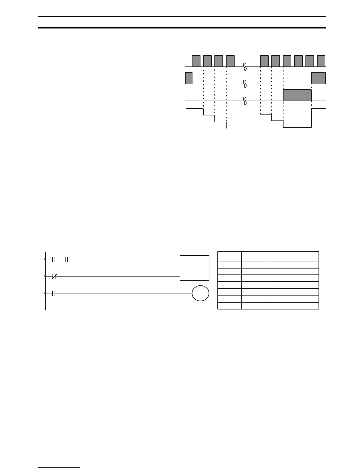
Changes in execution conditions, the Completion Flag, and the PV are illus-
trated below. PV line height is meant only to indicate changes in the PV.
Precautions Program execution will continue even if a non-BCD SV is used, but the SV will
not be correct.
Flags ER: SV is not in BCD.
Indirectly addressed DM word is non-existent. (Content of *DM word
is not BCD, or the DM area boundary has been exceeded.)
Example In the following example, CNT is used to create extended timers by counting
SR area clock pulse bits.
CNT 001 counts the number of times the 1-second clock pulse bit (SR 25502)
goes from OFF to ON. Here again, IR 00000 is used to control the times when
CNT is operating.
Because in this example the SV for CNT 001 is 700, the Completion Flag for
CNT 002 turns ON when 1 second x 700 times, or 11 minutes and 40 seconds
have expired. This would result in IR 01602 being turned ON.
!Caution The shorter clock pulses will not necessarily produce accurate timers
because their short ON times might not be read accurately during longer
cycles. In particular, the 0.02-second and 0.1-second clock pulses should not
be used to create timers with CNT instructions.
Execution condition
on count pulse (CP)
Execution condition
on reset (R)
ON
OFF
ON
OFF
Completion Flag
ON
OFF
PV
SV
SV – 1
SV – 2
0002
0001
0000
SV
CP
R
CNT
001
#0700
00000 25502
00001
CNT 001
01602
Address Instruction Operands
00000 LD 00000
00001 AND 25502
00002 LD NOT 00001
00003 CNT 001
# 0700
00004 LD CNT 001
00005 OUT 01602