125
Advanced I/O Instructions (CQM1 Only) Section 2-2
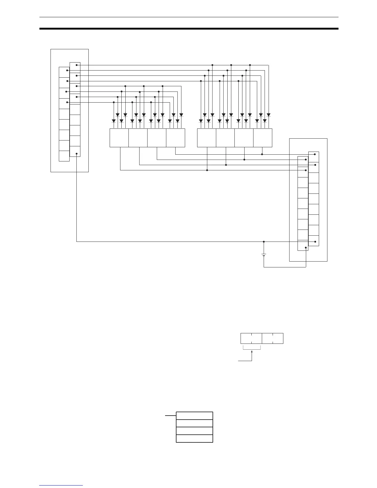
The following example illustrates connections for an A7B Thumbwheel Switch.
The inputs can be connected to the CPU Unit’s input terminals or a DC Input
Unit with 8 or more input points and the outputs can be connected from a
Transistor Output Unit with 8 or more output points.
Preparations When using DSW(87), make the following setting in the PC Setup in PRO-
GRAM mode before executing the program.
Digital Switch Settings (PC Setup)
Do not make any changes to bits 0 to 7. They are not related to DSW(87).
Using the Instruction
1
3
5
7
9
11
13
15
COM
0
2
4
6
8
10
12
14
COM
ID212
Input Unit
Switch no
.
8
1
3
5
7
9
11
13
15
COM
0
2
4
6
8
10
12
14
DC
OD212
1248
76 5 4 3 2 1C
Output Unit
A7B
Thumbwheel
Switch
Note The data read signal is not required in the example.
15 0
– –
Bit
DM6639
Number of digits to read
00: 4 digits
01: 8 digits
Default: 4 digits
DSW(87)
IW
OW
R
IW: Input word
OW: Output word
R: First register word

 Loading...


