83
CPM1/CPM1A Interrupt Functions Section 1-6
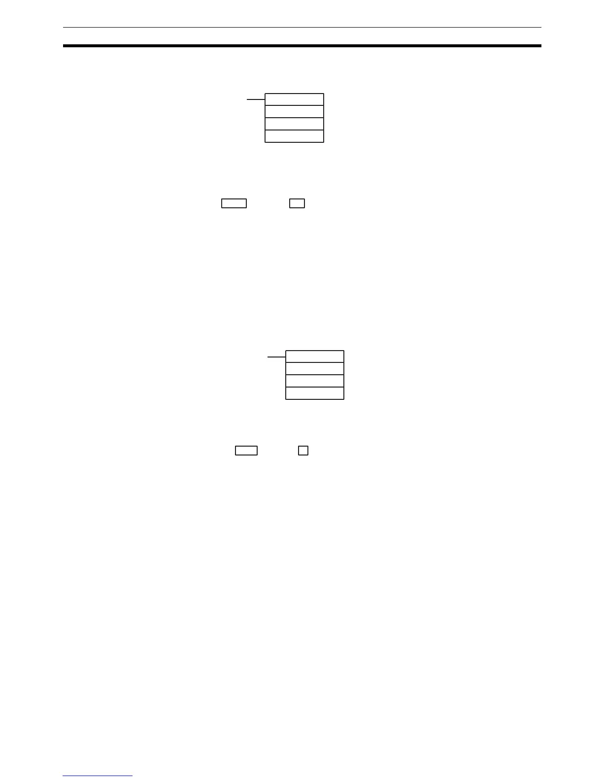
Using the PRV(62) Instruction
Read the PV of the high-speed counter by using the PRV(62) instruction.
The PV of the high-speed counter is stored as shown below. The leftmost bit
will be F for negative values.
The PV is read when the PRV(62) instruction is actually executed.
Changing the PV
There are two ways to change the PV of high-speed counter. The first way is
to reset it by using the reset methods. (In this case the PV is reset to 0.) The
second way is to use the INI(61) instruction.
The method using the INI(61) instruction is explained here. For an explanation
of the reset method, refer to the beginning of this description of high-speed
counter.
Change the timer PV by using the INI(61) instruction as shown below.
To specify a negative number in up/down mode, set F in the leftmost digit.
Application Example
(Incrementing Mode)
This example shows a program that uses the high-speed counter with single-
phase inputs in the Incrementing Mode, making comparisons by means of the
target matching method.
The comparison conditions (target values and count directions) are stored in
the comparison table with the subroutine numbers. Up to 16 target values can
be stored. The corresponding subroutine is executed when the counter’s PV
matches the target value.
The following data is stored for the comparison table:
DM 0000 0002 Number of comparison conditions: 2
DM 0001 1000 Target value 1: 1000
DM 0002 0000
DM 0003 0030 Comparison 1 interrupt subroutine no.: 30
DM 0004 2000 Target value 2: 2000
DM 0005 0000
DM 0006 0031 Comparison 2 interrupt subroutine no.: 31
(@)PRV(62)
000
000
P1
P1: Leading word of PV
Leftmost 4 digits Rightmost 4 digits Up/Down Mode Incrementing Mode
P1+1 P1 F0032767 to 00032767
(–32767)
00000000 to 00065535
Leftmost 4 digits Rightmost 4 digits Up/Down Mode Incrementing Mode
D+1 D F0032767 to 00032767 00000000 to 00065535
(@)INI(61)
000
002
D
D: Leading word for storing PV change data
 Loading...


