94
Communications Functions Section 1-9
Communications
Procedure
This section explains how to use the host link to execute data transmissions
from the CQM1. Using this method enables automatic data transmission from
the CQM1 when data is changed, and thus simplifies the communications
process by eliminating the need for constant monitoring by the computer.
1,2,3... 1. Check to see that AR 0805 (RS-232C Port Transmit Ready Flag) is ON.
2. Use the TXD(48) instruction to transmit the data.
From the time this instruction is executed until the data transmission is com-
plete, AR 0805 (or AR 0813 for the peripheral port) will remain OFF. It will turn
ON again upon completion of the data transmission. The TXD(48) instruction
does not provide for a response, so in order to receive confirmation that the
computer has received the data, the computer’s program must be written so
that it gives notification when data is written from the CQM1.
The transmission data frame is as shown below for data transmitted in the
Host Link Mode by means of the TXD(48) instruction.
To reset the RS-232C port (i.e., to restore the initial status), turn ON SR
25209. To reset the peripheral port, turn ON SR 25208. These bits will turn
OFF automatically after the reset.
If the TXD(48) instruction is executed while the CQM1 is in the middle of
responding to a command from the computer, the response transmission will
first be completed before the transmission is executed according to the
TXD(48) instruction. In all other cases, data transmission based on a TXD(48)
instruction will be given first priority.
Application Example This example shows a program for using the RS-232C port in the Host Link
Mode to transmit 10 bytes of data (DM 0000 to DM 0004) to the computer.
The default values are assumed for all the PC Setup (i.e., the RS-232C port is
used in Host Link Mode, the node number is 00, and the standard communi-
cations conditions are used.) From DM 0000 to DM 0004, “1234” is stored in
every word. From the computer, execute a program to receive CQM1 data
with the standard communications conditions.
The following type of program must be prepared in the host computer to
receive the data. This program allows the computer to read and display the
(@)TXD(48)
S
C
N
S: Beginning word no. of transmission data
C: Control data
Bits 00 to 03
0: Leftmost bytes first
1: Rightmost bytes first
Bits 12 to 15
0: RS-232C port
1: Peripheral port
N: Number of bytes of data to be sent (4 digits BCD)
0000 to 0256
@
Node
No.
EX
Header code
(Must be "EX")
Data (up to 122 characters) FCS Terminator
↵
x 10
0
x 10
1
*
@TXD(48)
DM 0000
#0000
#0010
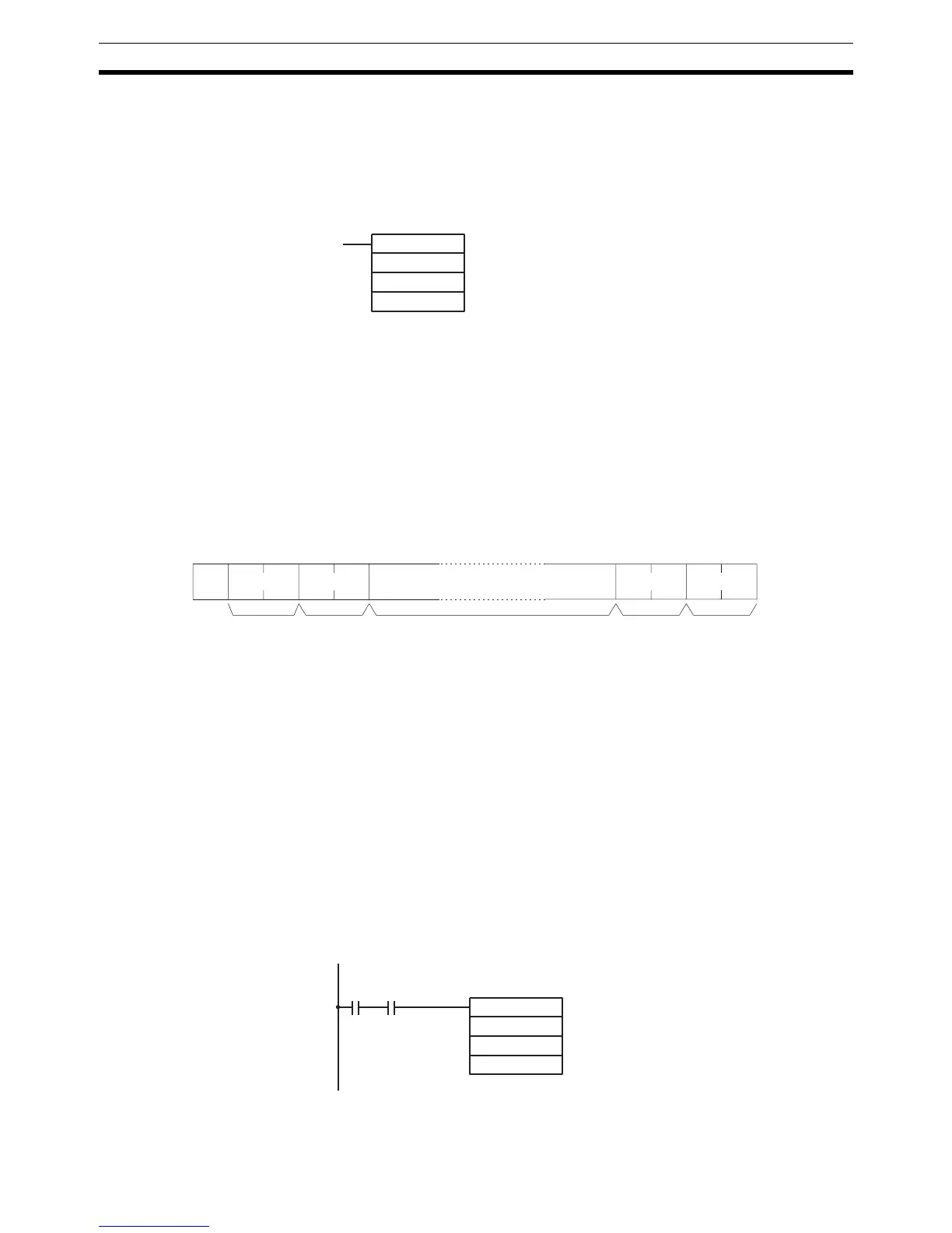
00100 AR0805
If AR 0805 (the Transmit Ready Flag) is ON
when IR 00100 turns ON, the ten bytes of
data (DM 0000 to DM 0004) will be trans-
mitted.
 Loading...


