107
Communications Functions Section 1-9
Limitations of One-to-one
Links with a SRM1
Only the 16 LR words from LR 00 to LR 15 can be linked in the SRM1, so use
only those 16 words in the CQM1 or C200HS when making a one-to-one link
with one of those PCs. A one-to-one link cannot be made to a SRM1 PC using
LR 16 through LR 63 in the CQM1 or C200HS.
PC Setup Settings The settings relating to 1-to-1 PC communications must be set as shown in
the following table.
Note 1. If an improper setting is used, a non-fatal error will occur, AR 1302 will be
turned ON, and the default setting (0 or 00) will be used.
2. For information on the 1-to-1 link settings for another OMRON PC, refer to
that PC’s Operation Manual.
3. If an out-of-range value is set, the following communications conditions will
result. In that case, reset the value so that it is within the permissible range.
Communications mode: Host Link
Communications format: Standard settings
(1 start bit, 7-bit data; even parity, 2 stop bits,
9,600 bps)
Transmission delay: No
Node number: 00
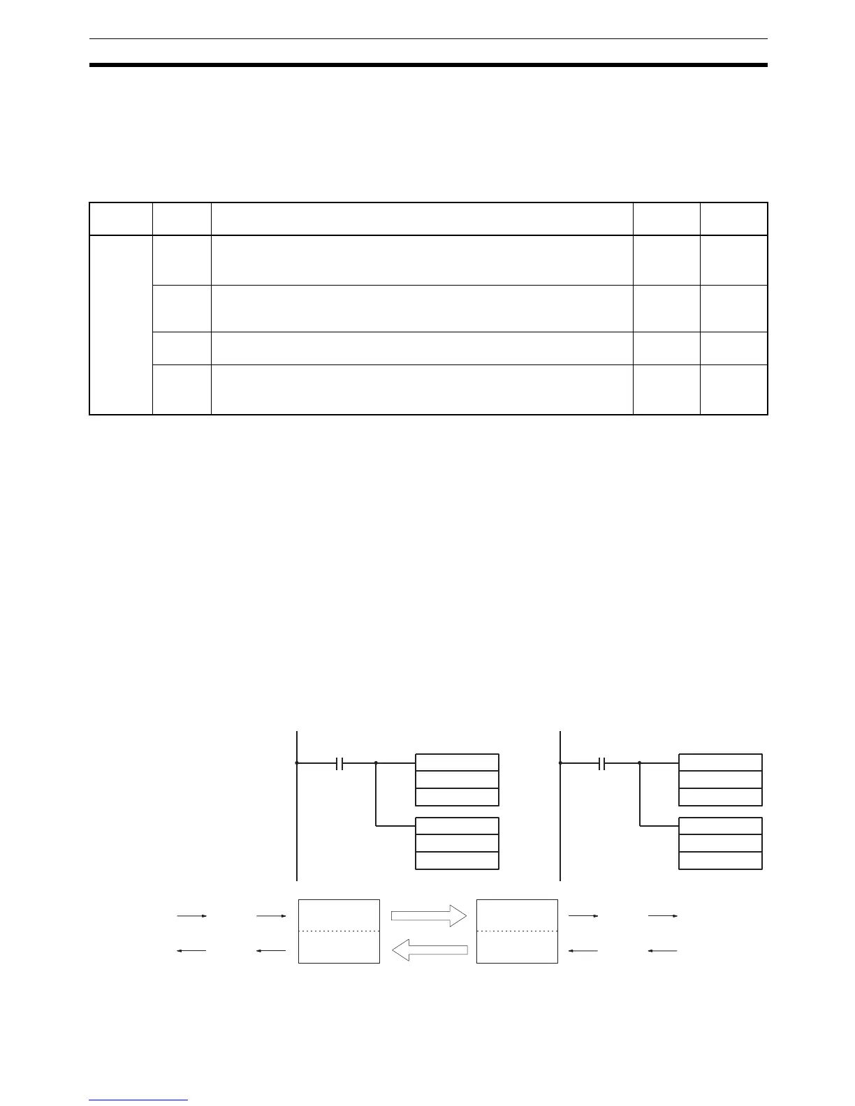
Example Program This example shows ladder programs that copy the status of IR 000 in each
SRM1 to SR 200 in the other SRM1.
Word Bit Function Setting
(Master)
Setting
(Slave)
DM 6645 00 to 03
Port settings
1
00: Standard (1 start bit, 7-bit data, even parity, 2 stop bits, 9,600 bps)
01: Settings in DM 6651
Any Any
04 to 07 CTS Control settings
0: Disable
1: Set
00
08 to 11 Link area for one-to-one PC link via peripheral port
0: LR 00 to LR 15
00
12 to 15
Communications mode
1
0: Host link; 1: No protocol; 2: 1-to-1 PC link (slave); 3: 1-to-1 PC link (mas-
ter); 4: NT link
32
25313 (Always ON)
MOV(21)
000
LR00
MOV(21)
LR08
200
Program in the Master
MOV(21)
000
LR08
MOV(21)
LR00
200
25313 (Always ON)
Program in the Slave
LR00
LR07
LR08
LR00
LR07
LR08
LR15
Writing area
Reading area
Write
Read
Reading area
Writing area
LR15
Write
Read
IR 000
SR 200
IR 000
SR 200

 Loading...


