128
Advanced I/O Instructions (CQM1 Only) Section 2-2
If only four digits are displayed, then only word S will be used.
Set Values for Selecting Logic and Number of Digits (C)
Note Do not set C to values other than 000 to 007.
SR 25409 will turn ON while 7SEG(88) is being executed.
Note 1. Do not use 7SEG(88) more than once within the same program.
2. Consider the cycle time and the characteristics of the 7-segment display
when designing the system.
3. Output bits not used here can be used as ordinary output bits.
With this instruction, 4 digits or 8 digits are displayed in 12 cycles.
Operation will proceed from the first execution without regard to the status
prior to execution.
Application Example This example shows a program for displaying the CQM1’s 8-digit BCD num-
bers at the 7-segment LED display. Assume that the 7-segment display is
connected to output word IR 100. Also assume that the Output Unit is using
negative logic, and that the 7-segment display logic is also negative for data
signals and latch signals.
Number of digits displayed Display Unit data input and
Output Unit logic
Display Unit latch input and
Output Unit logic
C setting data
4 digits (4 digits, 1 block) Same Same 000
Different 001
Different Same 002
Different 003
8 digits (4 digits, 2 blocks) Same Same 004
Different 005
Different Same 006
Different 007
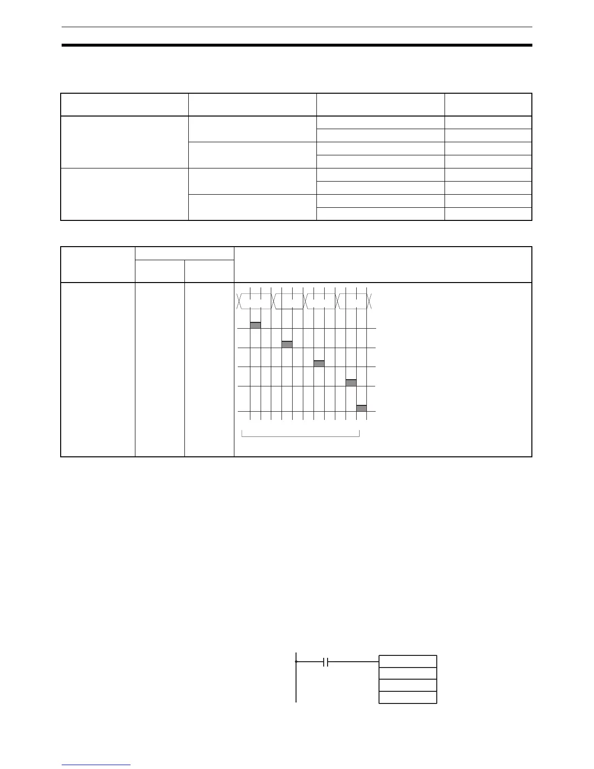
Function Bit(s) in O Output status (Data and latch logic depends on C)
(4 digits, 1
block)
(4 digits, 2
blocks)
 Loading...


