160
Basic Ladder Diagrams Section 4-3
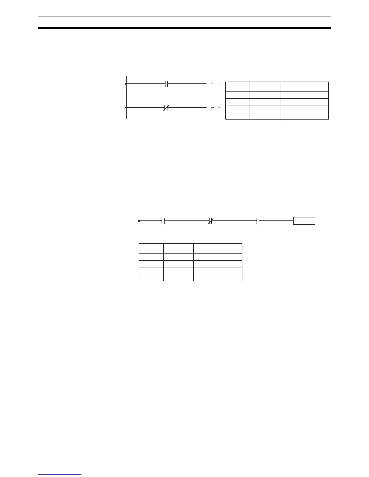
LOAD and LOAD NOT The first condition that starts any logic block within a ladder diagram corre-
sponds to a LOAD or LOAD NOT instruction. Each of these instruction
requires one line of mnemonic code. “Instruction” is used as a dummy instruc-
tion in the following examples and could be any of the right-hand instructions
described later in this manual.
When this is the only condition on the instruction line, the execution condition
for the instruction at the right is ON when the condition is ON. For the LOAD
instruction (i.e., a normally open condition), the execution condition would be
ON when IR 00000 was ON; for the LOAD NOT instruction (i.e., a normally
closed condition), it would be ON when 00000 was OFF.
AND and AND NOT When two or more conditions lie in series on the same instruction line, the first
one corresponds to a LOAD or LOAD NOT instruction; and the rest of the con-
ditions, to AND or AND NOT instructions. The following example shows three
conditions which correspond in order from the left to a LOAD, an AND NOT,
and an AND instruction. Again, each of these instructions requires one line of
mnemonic code.
The instruction would have an ON execution condition only when all three
conditions are ON, i.e., when IR 00000 was ON, IR 00100 was OFF, and LR
0000 was ON.
AND instructions in series can be considered individually, with each taking the
logical AND of the execution condition (i.e., the total of all conditions up to that
point) and the status of the AND instruction’s operand bit. If both of these are
ON, an ON execution condition will be produced for the next instruction. If
either is OFF, the result will also be OFF. The execution condition for the first
AND instruction in a series is the first condition on the instruction line.
Each AND NOT instruction in a series would take the logical AND between its
execution condition and the inverse of its operand bit.
00000
00000
A LOAD instruction.
A LOAD NOT instruction.
Address Instruction Operands
00000 LD 00000
00001 Instruction
00002 LD NOT 00000
00003 Instruction
00000 00100 LR 0000
Instruction
Address Instruction Operands
00000 LD 00000
00001 AND NOT 00100
00002 AND LR 0000
00003 Instruction