167
Basic Ladder Diagrams Section 4-3
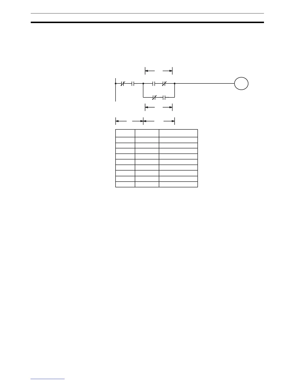
When coding the logic block instructions together at the end of the logic
blocks they are combining, they must, as shown below, be coded in reverse
order, i.e., the logic block instruction for the last two blocks is coded first, fol-
lowed by the one to combine the execution condition resulting from the first
logic block instruction and the execution condition of the logic block third from
the end, and on back to the first logic block that is being combined.
Complicated Diagrams When determining what logic block instructions will be required to code a dia-
gram, it is sometimes necessary to break the diagram into large blocks and
then continue breaking the large blocks down until logic blocks that can be
coded without logic block instructions have been formed. These blocks are
then coded, combining the small blocks first, and then combining the larger
blocks. Either AND LOAD or OR LOAD is used to combine the blocks, i.e.,
AND LOAD or OR LOAD always combines the last two execution conditions
that existed, regardless of whether the execution conditions resulted from a
single condition, from logic blocks, or from previous logic block instructions.
When working with complicated diagrams, blocks will ultimately be coded
starting at the top left and moving down before moving across. This will gener-
ally mean that, when there might be a choice, OR LOAD will be coded before
AND LOAD.
00000 00001 00002 00003
10002
00004 00202
Block
a
Block
b
Block
b2
Block
b1
Address Instruction Operands
00000 LD NOT 00000
00001 AND 00001
00002 LD 00002
00003 AND NOT 00003
00004 LD NOT 00004
00005 AND 00202
00006 OR LD
–
00007 AND LD
–
00008 OUT 10002

 Loading...


