180
Work Bits (Internal Relays) Section 4-5
Work Bit Applications Examples given later in this subsection show two of the most common ways
to employ work bits. These should act as a guide to the almost limitless num-
ber of ways in which the work bits can be used. Whenever difficulties arise in
programming a control action, consideration should be given to work bits and
how they might be used to simplify programming.
Work bits are often used with the OUTPUT, OUTPUT NOT, DIFFERENTIATE
UP, DIFFERENTIATE DOWN, and KEEP instructions. The work bit is used
first as the operand for one of these instructions so that later it can be used as
a condition that will determine how other instructions will be executed. Work
bits can also be used with other instructions, e.g., with the SHIFT REGISTER
instruction (SFT(10)). An example of the use of work words and bits with the
SHIFT REGISTER instruction is provided in 5-16-1 SHIFT REGISTER –
SFT(10).
Although they are not always specifically referred to as work bits, many of the
bits used in the examples in SECTION 5 Instruction Set use work bits. Under-
standing the use of these bits is essential to effective programming.
Reducing Complex
Conditions
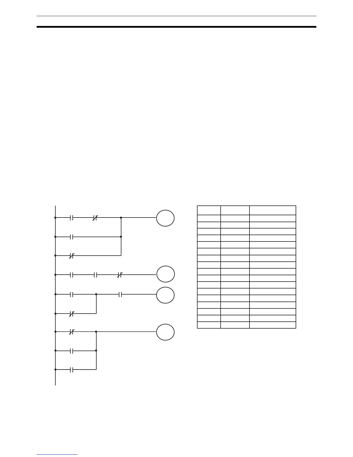
Work bits can be used to simplify programming when a certain combination of
conditions is repeatedly used in combination with other conditions. In the fol-
lowing example, IR 00000, IR 00001, IR 00002, and IR 00003 are combined
in a logic block that stores the resulting execution condition as the status of
IR 21600. IR 21600 is then combined with various other conditions to deter-
mine output conditions for IR 10000, IR 10001, and IR 10002, i.e., to turn the
outputs allocated to these bits ON or OFF.
Differentiated Conditions Work bits can also be used if differential treatment is necessary for some, but
not all, of the conditions required for execution of an instruction. In this exam-
ple, IR 10000 must be left ON continuously as long as IR 001001 is ON and
both IR 00002 and IR 00003 are OFF, or as long as IR 00004 is ON and IR
00000
00003
00001
00004
00002
00005
00004
00007
00006
0000521600
21600
21600
21600
10000
10001
10002
Address Instruction Operands
00000 LD 00000
00001 AND NOT 00001
00002 OR 00002
00003 OR NOT 00003
00004 OUT 21600
00005 LD 21600
00006 AND 00004
00007 AND NOT 00005
00008 OUT 10000
00009 LD 21600
00010 OR NOT 00004
00011 AND 00005
00012 OUT 10001
00013 LD NOT 21600
00014 OR 00006
00015 OR 00007
00016 OUT 10002