275
Conversion Instructions Section 5-19
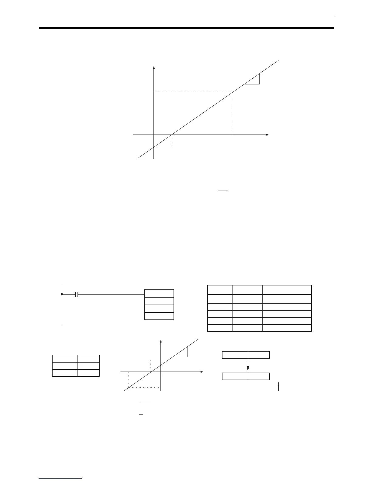
The following diagram shows the source word, S, converted to R according to
the line defined by the point (P1, 0) and slope
∆Y/∆X.
The result can be calculated by first converting all signed hexadecimal values
to BCD and then using the following formula.
Flags ER: Indirectly addressed DM word is non-existent. (Content of *DM word
is not BCD, or the DM area boundary has been exceeded.)
P1 and P1+2 are not in the same data area, or other setting error.
CY: ON when the result, R, is negative.
EQ: ON when the result, R, is 0000.
Example When 05000 is turned ON in the following example, the signed binary source
data in 001 (#FFE2) is converted to BCD according to the parameters in
DM 0000 to DM 0002. The result (#0018) is then written to LR 00 and CY is
turned ON because the result is negative.
S
Value after conversion
(BCD)
R
Value before conversion
(Signed hexadecimal)
X-intercept
∆X
∆ Y
R = × (S–P1)
∆X
∆Y
@SCL2(––)
DM 0000
001
05000
LR 00
Address Instruction Operands
00000 LD 05000
00001 @SCL2(––)
001
DM 0000
LR 00
DM 0000 FFFD
DM 0001 0003
DM 0002 0002
IR 001 FFE2
LR 00 0018
FFFD
3
2
CY=1
FFE2
–0018
CY flag is turned ON because
the conversion result is negative.
R = × (FFE2–FFFD)
0003
0002
= × (–1B) = –18
3
2

 Loading...


