341
Special Instructions Section 5-26
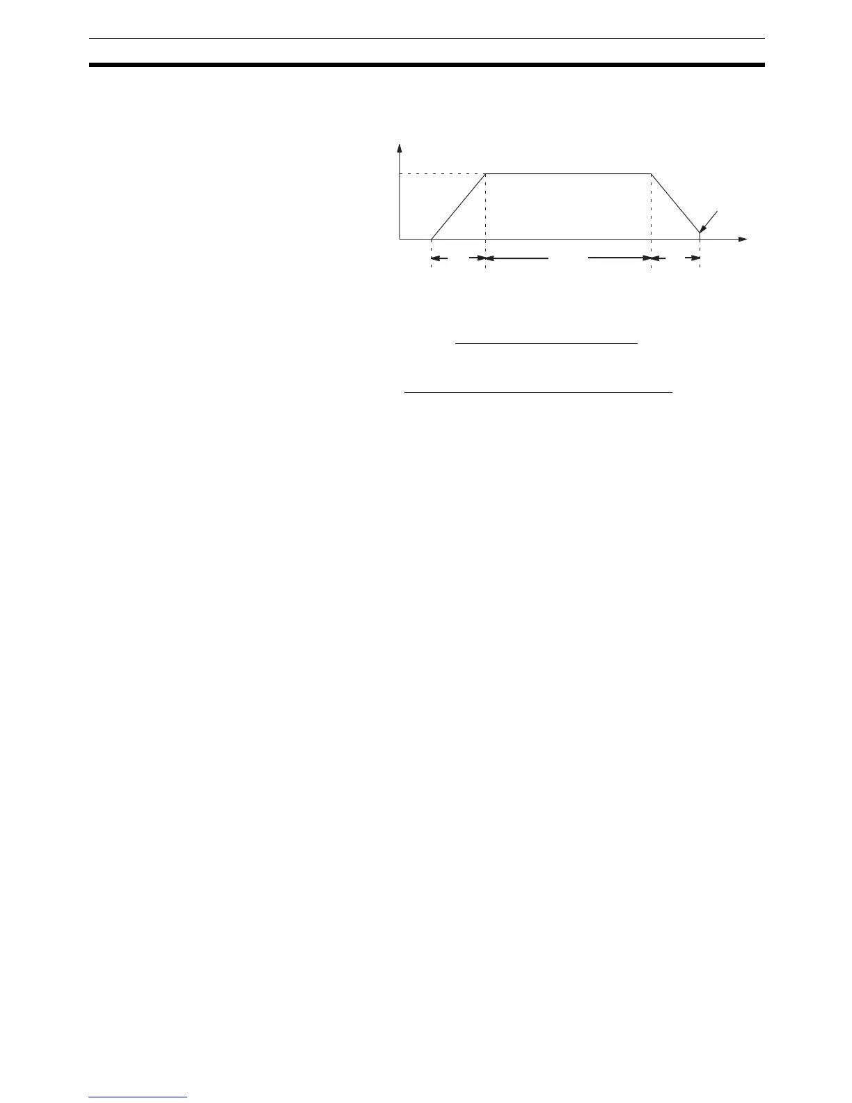
Description PLS2(––) is used to output a specified number of CW or CCW pulses from
port 1 or 2. The pulse output accelerates to the target frequency at a specified
rate and decelerates at the same rate. (Pulse output stops at 100 Hz.)
The following equations show how to calculate the approximate acceleration/
deceleration time T
1
and running time T
2
. Both times are in seconds.
Note 1. Although T
1
and T
2
will vary slightly depending on the operating condi-
tions, the number of pulses output will be accurate.
2. PLS2(––) will not operate if pulses are already being output from the spec-
ified port. Check the pulse output flags (AR 0515 for port 1 and AR 0615
for port 2) before executing PLS2(––).
3. Refer to 1-3 Pulse Output Function (CQM1 Only) for more details.
Operand Settings P specifies the port where the pulses will be output. Pulses are output from
port 1 when P=001, and pulses are output from port 2 when P=002.
D specifies whether the output signal is clockwise (CW) or counter-clockwise
(CCW). The output is CW when D=000 and CCW when D=001.
The content of C determines the acceleration/deceleration rate. During accel-
eration or deceleration, the output frequency is increased or decreased by the
amount set in C every 4.08 ms. C must be BCD from 0001 to 0200 (10 Hz to
2kHz).
The content of C+1 specifies the target frequency. C+1 must be BCD from
0010 to 5000 (100 Hz to 50 kHz).
The 8-digit content of C+3,C+2 determines the number of pulses that will be
output. C+3, C+2 must be BCD between 0000 0001 and 1677 7215.
Flags ER: There is an error in the operand settings.
The CPU Unit is not a CQM1-CPU43-EV1.
The PC Setup is not set for pulse output.
The target frequency, acceleration/deceleration rate, and number of
pulses are incorrect. (Number of pulses < T
1
× Target frequency)
PLS2(––) is executed in an interrupt subroutine while a pulse I/O or
high-speed counter instruction is being executed in the main program.
A data area boundary has been exceeded.
Indirectly addressed DM word is non-existent. (Content of *DM word is
not BCD, or the DM area boundary has been exceeded.)
AR 0515: Port 1 output flag. ON when pulses are being output from port 1.
AR 0615: Port 2 output flag. ON when pulses are being output from port 2.
Target frequency
T
1
T
1
T
2
100 Hz
T
1
≅ 0.004 ×
Acceration / deceleration rate
Target frequency
T
2
≅
Number of pulses – (T
1
× Target frequency)
Target frequency

 Loading...


