351
Communications Instructions Section 5-27
TXD(48) operates differently in host link mode and RS-232C mode, so these
modes are described separately.
Note 1. Flag AR 0805 will be ON when the CQM1 or SRM1
is capable of transmitting data through the RS-232C port and AR 0813 will
be ON when the CQM1 or SRM1 is capable of transmitting data through
the peripheral port.
2. Refer to 1-9 Communications Functions for details on using the TXD(48)
instruction, setting communications protocol in the PC Setup, etc.
Host Link Mode N must be BCD from #0000 to #0061 (i.e., up to 122 bytes of ASCII). The
value of the control word determines the port from which data will be output,
as shown below.
The specified number of bytes will be read from S through S+(N/2)–1, con-
verted to ASCII, and transmitted through the specified port. The bytes of
source data shown below will be transmitted in this order: 12345678...
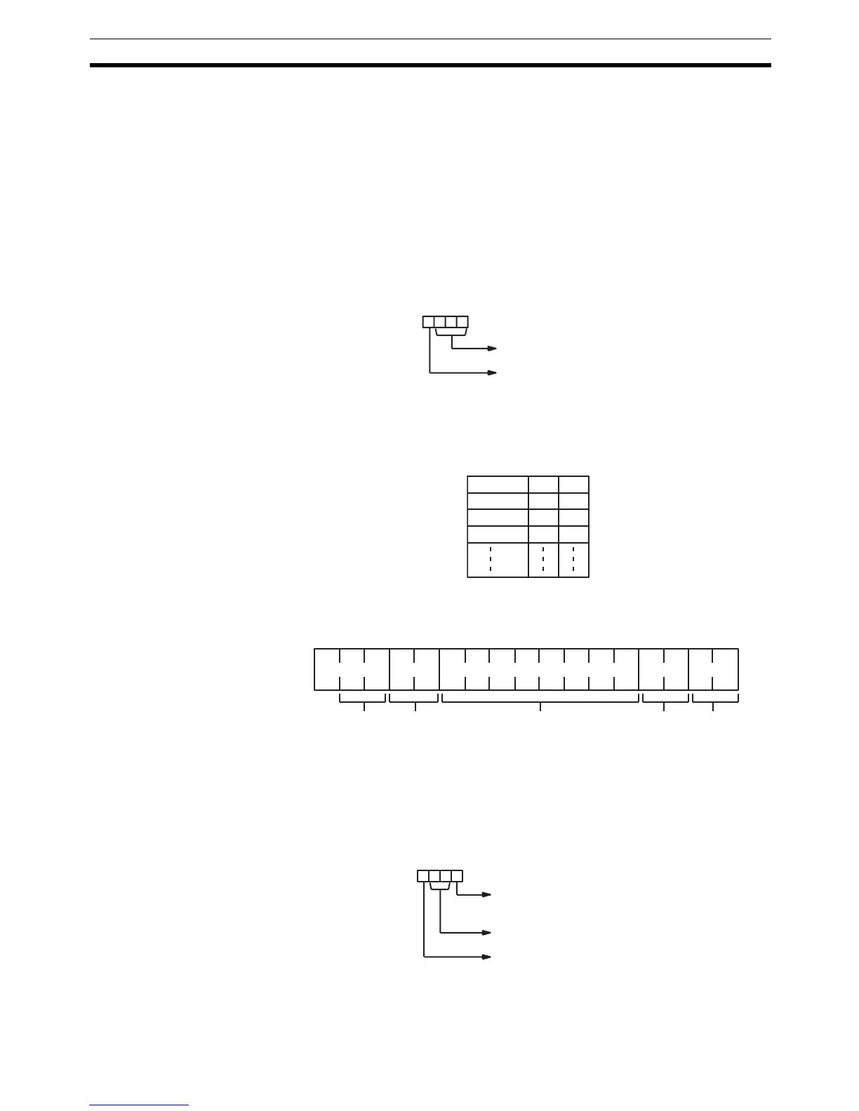
The following diagram shows the format for host link command (TXD) sent
from the CQM1. The CQM1 automatically attaches the prefixes and suffixes,
such as the node number, header, and FCS.
RS-232C Mode N must be BCD from #0000 to #00256. The value of the control word deter-
mines the port from which data will be output and the order in which data will
be written to memory.
Control Word The value of the control word determines the port from which data will be read
and the order in which data will be written to memory.
Not used. (Set to 000.)
Port 0: Specifies RS-232C port.
1: Specifies peripheral port.
Digit number: 3 2 1 0
MSB LSB
S12
S+1 3 4
S+2 5 6
S+3 7 8
@ X X X X X X ......... X X X CR
Header
code
Data (122 ASCII characters max.) FCSNode
number
Terminator
Byte order 0: Most significant bytes first
1: Least significant bytes first
Not used. (Set to 00.)
Port 0: Specifies RS-232C port.
1: Specifies peripheral port.
Digit number: 3 2 1 0