353
Communications Instructions Section 5-27
N determines which part of the RS-232C Setup is changed.
If S is a word address, the contents of S through S+4 are copied to the 5
words in the PC Setup that contain the settings for the port specified by N.
If S is input as the constant #0000, the settings for the specified port are
returned to their default values.
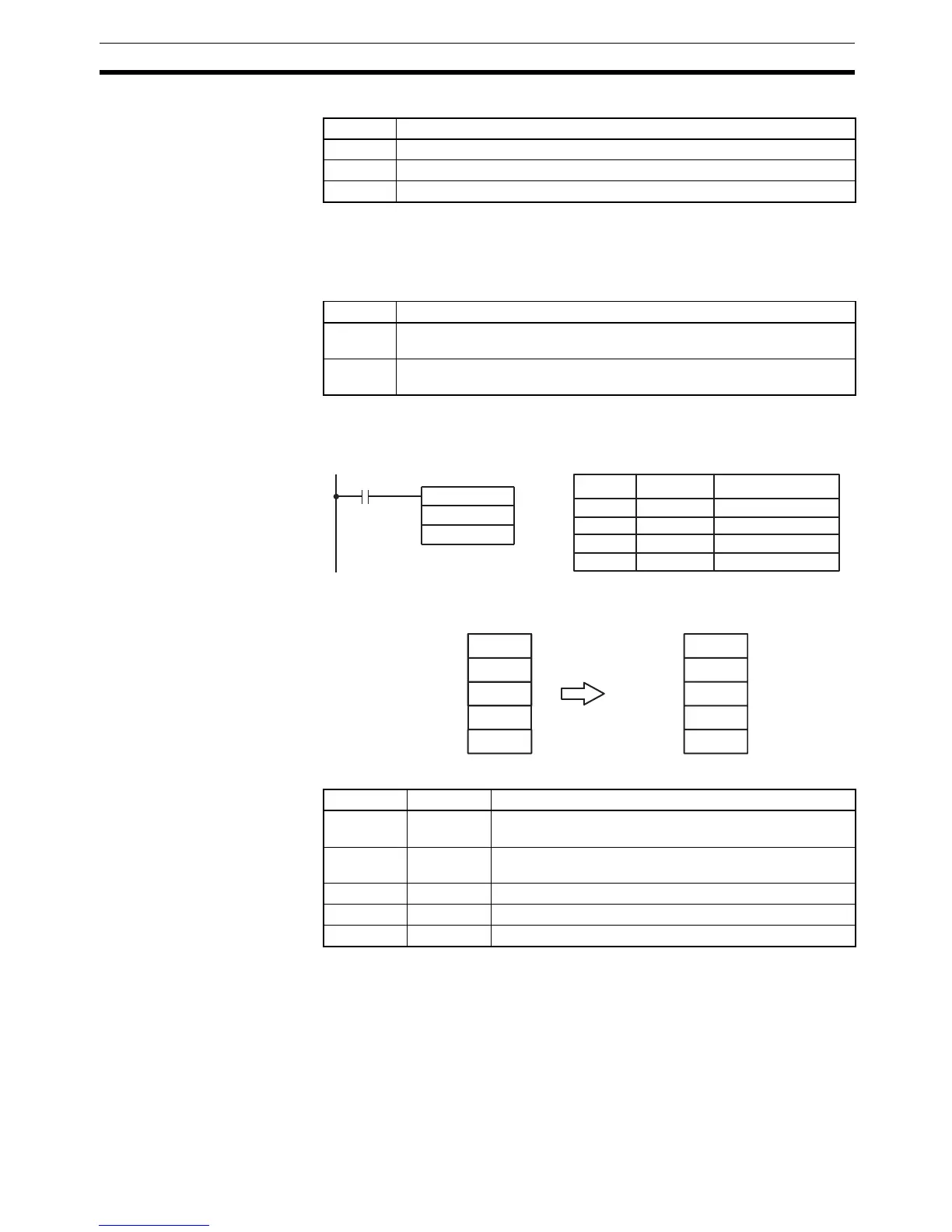
Application Example This example shows a program that transfers the contents of DM 0100
through DM 0104 to the PC Setup area for Communications Board port A
(DM 6555 through DM 6569).
The settings are transferred as shown below. The Changing RS-232C Setup
Flag (SR 27504) will be turned OFF when the transfer has been completed.
The following table shows the function of the transferred setup data.
Flags ER: Indirectly addressed DM word is non-existent. (Content of *DM word
is not BCD, or the DM area boundary has been exceeded.)
The port specifier (N) isn’t IR 000, IR 001, or IR 002.
Port A has been specified, but pin 2 of the DIP switch is ON.
The PC Setup is write-protected. (Pin 1 of the DIP switch is ON.)
The specified source words exceed the data area.
The instruction was executed from an interrupt program.
NSpecified Port
IR 000 Built-in RS-232C port (PC Setup: DM 6645 to DM 6649)
IR 001 Communications Board port A (PC Setup: DM 6555 to DM 6559)
IR 002 Communications Board port B (PC Setup: DM 6550 to DM 6554)
SFunction
Word
address
The contents of S through S+4 are copied to the part of the PC Setup that
contains the settings for the port specified by N.
Constant
(#0000)
The settings for the port specified by N are returned to their default val-
ues.
Word Content Function
DM 0100 1001 Enables the communications settings in DM 0101 and
sets the communications mode to RS-232C.
DM 0101 0803 Sets the following communications settings:
9,600 bps, 1 start bit, 8-bit data, 1 stop bit, no parity
DM 0102 0000 No transmission delay (0 ms)
DM 0103 2000 Enables the end code CR, LF.
DM 0104 0000 ---
@STUP(––)
001
DM 0100
00000
Address Instruction Operands
00000 LD 00000
00001 @STUP(––)
001
DM 0100

 Loading...


