415
CPM1/CPM1A Cycle Time and I/O Response Time Section 7-2
7-2-5 Interrupt Processing Time
This section explains the processing times involved from the time an interrupt
is executed until the interrupt processing routine is called, and from the time
an interrupt processing routine is completed until returning to the initial loca-
tion. This explanation applies to input interrupts, interval timer interrupts, and
high-speed counter interrupts.
1,2,3... 1. Source of interrupt
2. Interrupt ON delay
3. Wait for completion of interrupt-mask processing
4. Change to interrupt processing
5. Interrupt routing (CPM1A only)
6. Return to initial location
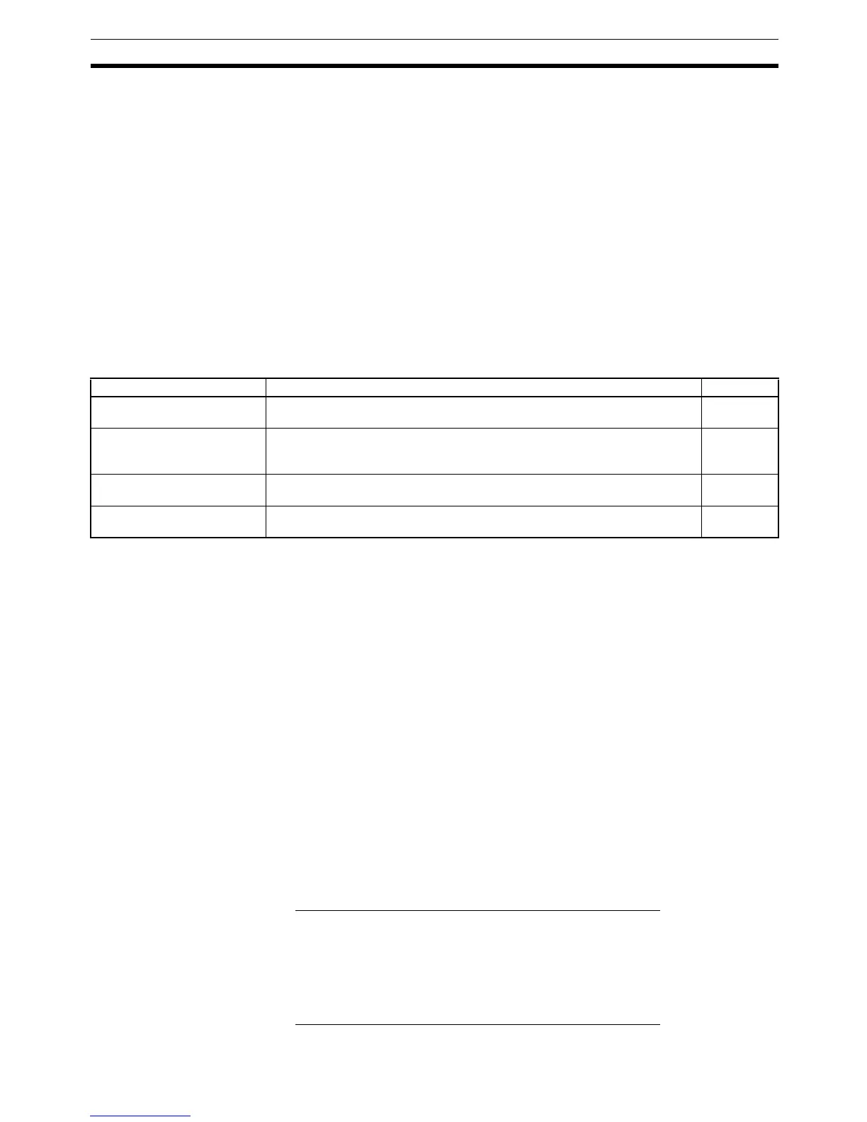
The table below shows the times involved from the generation of an interrupt
signal until the interrupt processing routine is called, and from when the inter-
rupt processing routine is completed until returning to the original position.
Mask Processing
Interrupts are masked during processing of the operations described below.
Until the processing is completed, any interrupts will remain masked for the
indicated times.
Generation and clearing of non-fatal errors:
When a non-fatal error is generated and the error contents are registered
at the CPM1, or when an error is being cleared, interrupts will be masked
for a maximum of 100 µs until the processing has been completed.
Online editing:
Interrupts will be masked for a maximum of 600 ms (i.e.: editing DM 6144
to DM 6655) when online editing is executed during operation. In addition,
the system processing may have to wait for a maximum of 170
µs during
this processing.
Example Calculation This example shows the interrupt response time (i.e., the time from when the
interrupt input turns ON until the start of the interrupt processing routine)
when input interrupts are used under the conditions shown below.
Minimum Response Time
Interrupt ON delay: 100
µs
Interrupt mask standby time: 0
µs
+ Change-to-interrupt processing: 30
µs
Minimum response time: 130
µs
Maximum Response Time
(Except for the Online Editing of DM 6144 to DM6655)
Interrupt ON delay: 100
µs
Interrupt mask standby time: 170
µs
+ Change-to-interrupt processing: 30
µs
Maximum response time: 300 µs
Item Contents Time
Interrupt ON delay This is the delay time from the time the interrupt input bit turns ON until the
time that the interrupt is executed. This is unrelated to other interrupts.
100 µs
Wait for completion of
interrupt-mask processing
This is the time during which interrupts are waiting until processing has been
completed. This situation occurs when a mask processes is executed. It is
explained below in more detail.
See below.
Change to interrupt
processing
This is the time it takes to change processing to an interrupt. 30 µs
Return This is the time it takes, from execution of RET(93), to return to the process-
ing that was interrupted.
30 µs

 Loading...


