439
Operating Errors Section 8-5
CPM1/CPM1A/SRM1 Non-fatal Errors
Note ** is 01 to 99 or 9B.
8-5-2 Fatal Errors
PC operation and program execution will stop and all outputs from the PC will
be turned OFF when any of these errors have occurred.
All CPU Unit indicators will be OFF for the power interruption error. For all
other fatal operating errors, the POWER and ERR/ALM indicators will be lit.
The RUN indicator will be OFF.
CQM1 Fatal Errors
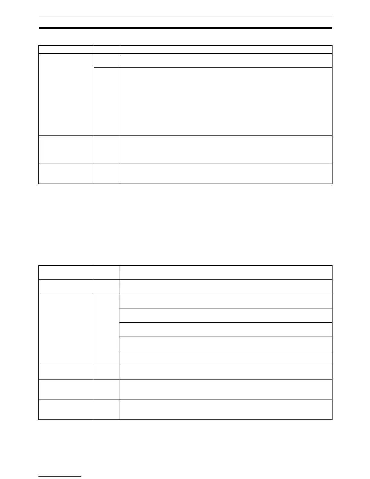
Message FAL No. Meaning and appropriate response
SYS FAIL FAL** (see
note)
01 to 99 An FAL(06) instruction has been executed in the program. Check the FAL number to
determine conditions that would cause execution, correct the cause, and clear the error.
9B An error has been detected in the PC Setup. Check flags AR 1300 to AR 1302, and cor-
rect as directed.
AR 1300 ON: An incorrect setting was detected in the PC Setup (DM 6600 to DM 6614)
when power was turned on. Correct the settings in PROGRAM Mode and turn on the
power again.
AR 1301 ON: An incorrect setting was detected in the PC Setup (DM 6615 to DM 6644)
when switching to RUN Mode. Correct the settings in PROGRAM Mode and switch to
RUN Mode again.
AR 1302 ON: An incorrect setting was detected in the PC Setup (DM 6645 to DM 6655)
during operation. Correct the settings and clear the error.
SCAN TIME OVER F8 Watchdog timer has exceeded 100 ms. (SR 25309 will be ON.)
This indicates that the program cycle time is longer than recommended. Reduce cycle
time if possible. (The CPM1/CPM1A/SRM1 can be set so that this error won’t be
detected.)
Communication
Errors (no message)
None If an error occurs in communications through the peripheral port or RS-232C port, the
COMM indicator will be off. The error flag in AR0812 will be ON. Check the connecting
cables and restart.
Message FALS
No.
Meaning and appropriate response
Power interruption
(no message)
None Power has been interrupted for at least 10 ms. Check power supply voltage and power
lines. Try to power-up again.
MEMORY ERR F1 AR 1611 ON: A checksum error has occurred in the PC Setup (DM 6600 to DM 6655).
Initialize all of the PC Setup and reinput.
AR 1612 ON: A checksum error has occurred in the program, indicating an incorrect
instruction. Check the program and correct any errors detected.
AR 1613 ON: A checksum error has occurred in an expansion instruction’s data. Initial-
ize all of the expansion instruction settings and reinput.
AR 1614 ON: Memory Cassette was installed or removed with the power on. Turn the
power off, install the Memory Cassette, and turn the power on again.
AR 1615 ON: The Memory Cassette contents could not be read at start-up. Check flags
AR 1412 to AR 1415 to determine the problem, correct it, and turn on the power again.
NO END INST F0 END(01) is not written anywhere in program. Write END(01) at the final address of the
program.
I/O BUS ERR C0 An error has occurred during data transfer between the CPU Unit and an I/O Unit.
Determine the location of the problem using flags AR 2408 to AR 2415, turn the power
off, check for loose I/O Units or end covers, and turn on the power again.
I/O UNIT OVER E1 The number of I/O words on the installed I/O Units exceeds the maximum. Turn off the
power, rearrange the system to reduce the number of I/O words, and turn on the power
again.

 Loading...


