EasyManuals Logo

Omron CPM1 Programming Manual

Omron CPM1
541 pages
To Next Page IconTo Next Page
To Previous Page IconTo Previous Page
Page #469 background imageLoading...
Page #469 background image
448
Troubleshooting Flowcharts Section 8-8
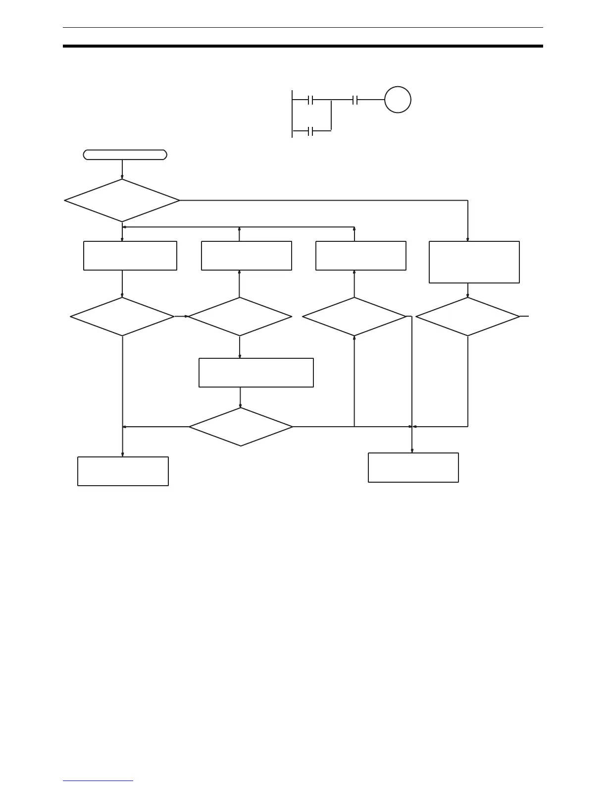
I/O Check The I/O check flowchart is based on the following ladder diagram section.
Note The CPM1 PC doesn’t have the IR 10500 output indicator. Substitute with one
from IR 01000 to IR 01915.
10500
00002
(LS1)
00003
(LS2)
SOL1 malfunction.
SOL1
10500
Ye s
Monitor the ON/OFF
status of IR 10500
with a Peripheral
Device.
No
Is the IR 10500 out-
put indicator operat-
ing normally?
Check the voltage at the
IR 10500 terminals.
Wire correctly. Replace terminal
connector.
Operation
O.K.?
Start
Is output wiring
correct?
Is terminal
block making prop-
er contact?
Disconnect the external wires
and check the conductivity of
each wire.
No
Ye s
Check output device
SOL1.
Operation
O.K.?
Replace the Output
Unit.
Ye s
No
No
Ye s
No
Operation
O.K.?
NoYe s
Ye s
A
To
next
page
(See note)

Table of Contents

Other manuals for Omron CPM1

Questions and Answers:

Question and Answer IconNeed help?

Do you have a question about the Omron CPM1 and is the answer not in the manual?

Omron CPM1 Specifications

General IconGeneral
ModelCPM1
ManufacturerOmron
Instruction SetBasic and advanced instructions
Power Supply100 to 240 VAC or 24 VDC
CommunicationRS-232C
I/O Points10, 20, 30, or 40 points depending on the model
TimersYes, multiple timers available
CountersYes, multiple counters available
Input Voltage24V DC
Output TypeRelay or transistor
Number of I/O Points10, 20, 30, 40
Communication PortsRS-232C (optional)
Operating Temperature0°C to 55°C
Storage Temperature-20°C
Humidity10% to 90% (non-condensing)
DimensionsVaries depending on the model
WeightVaries depending on the model
Program Memory2048 steps (2K steps)

Related product manuals