462
Memory Areas Appendix C
Note 1. IR and LR bits that are not used for their allocated functions can be used as work bits.
2. At least 2,720 bits can be used as work bits. The total number of bits that can be used depends on
the configuration of the PC system.
3. When accessing a PV, TC numbers are used as word data; when accessing Completion Flags, they
are used as bit data.
4. Although the CQM1-CPU11-E and CQM1-CPU21-E do not support DM 1024 through DM 6143, an
error will not occur if they are addressed. Any attempt to write to these words will have no effect and
any reads will produce all zeros.
5. Data in DM 6144 to DM 6655 cannot be overwritten from the program.
SR Area
These bits mainly serve as flags related to CQM1 operation. The following
table provides details on the various bit functions.
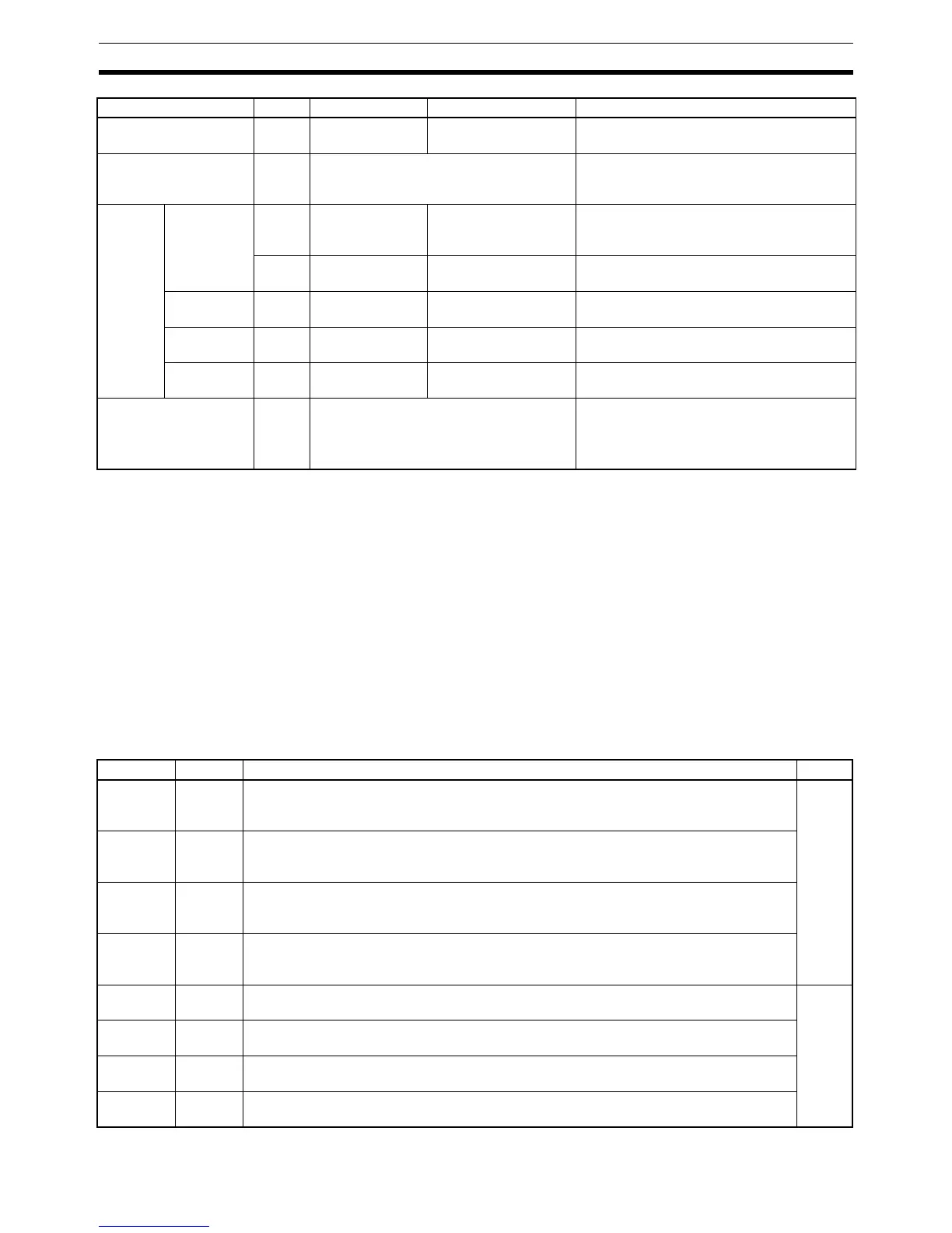
LR area
1
1,024
bits
LR 00 to LR 63 LR 0000 to LR 6315 Used for 1:1 data link through the RS-232
port.
Timer/Counter area
3
512
bits
TC 000 to TC 511 (timer/counter num-
bers)
The same numbers are used for both timers
and counters. TC 000 to TC 002 are used
for interval timers.
DM area Read/write 1,024
words
DM 0000 to
DM 1023
--- DM area data can be accessed in word
units only. Word values are retained when
the power is turned off.
5,120
words
DM 1024 to
DM 6143
--- Available in CQM1-CPU4@-EV1 only.
4
Read-only
5
425
words
DM 6144 to
DM 6568
--- Cannot be overwritten from program.
Error history
area
5
31
words
DM 6569 to
DM 6599
--- Used to store the time of occurrence and
error code of errors that occur.
PC Setup
5
56
words
DM 6600 to
DM 6655
--- Used to store various parameters that con-
trol PC operation.
User program area (UM
area)
3,200
or
7,200
words
--- Used to store the program. Retained when
the power is turned off.
CQM1-CPU11/21-E: 3,200 words
CQM1-CPU4@-EV1: 7,200 words
Data area Size Words Bits Function
Word Bit(s) Function Page
SR 244
00 to 15 Input Interrupt 0 Counter Mode SV
SV when input interrupt 0 is used in counter mode (4 digits hexadecimal, 0000 to FFFF).
(Can be used as work bits when input interrupt 0 is not used in counter mode.)
42
SR 245
00 to 15 Input Interrupt 1 Counter Mode SV
SV when input interrupt 1 is used in counter mode (4 digits hexadecimal, 0000 to FFFF).
(Can be used as work bits when input interrupt 1 is not used in counter mode.)
SR 246
00 to 15 Input Interrupt 2 Counter Mode SV
SV when input interrupt 2 is used in counter mode (4 digits hexadecimal, 0000 to FFFF).
(Can be used as work bits when input interrupt 2 is not used in counter mode.)
SR 247
00 to 15 Input Interrupt 3 Counter Mode SV
SV when input interrupt 3 is used in counter mode (4 digits hexadecimal, 0000 to FFFF).
(Can be used as work bits when input interrupt 3 is not used in counter mode.)
SR 248
00 to 15 Input Interrupt 0 Counter Mode PV Minus One
Counter PV-1 when input interrupt 0 is used in counter mode (4 digits hexadecimal).
42
SR 249
00 to 15 Input Interrupt 1 Counter Mode PV Minus One
Counter PV-1 when input interrupt 1 is used in counter mode (4 digits hexadecimal).
SR 250
00 to 15 Input Interrupt 2 Counter Mode PV Minus One
Counter PV-1 when input interrupt 2 is used in counter mode (4 digits hexadecimal).
SR 251
00 to 15 Input Interrupt 3 Counter Mode PV Minus One
Counter PV-1 when input interrupt 3 is used in counter mode (4 digits hexadecimal).

 Loading...


