28
Pulse Output Function (CQM1 Only) Section 1-3
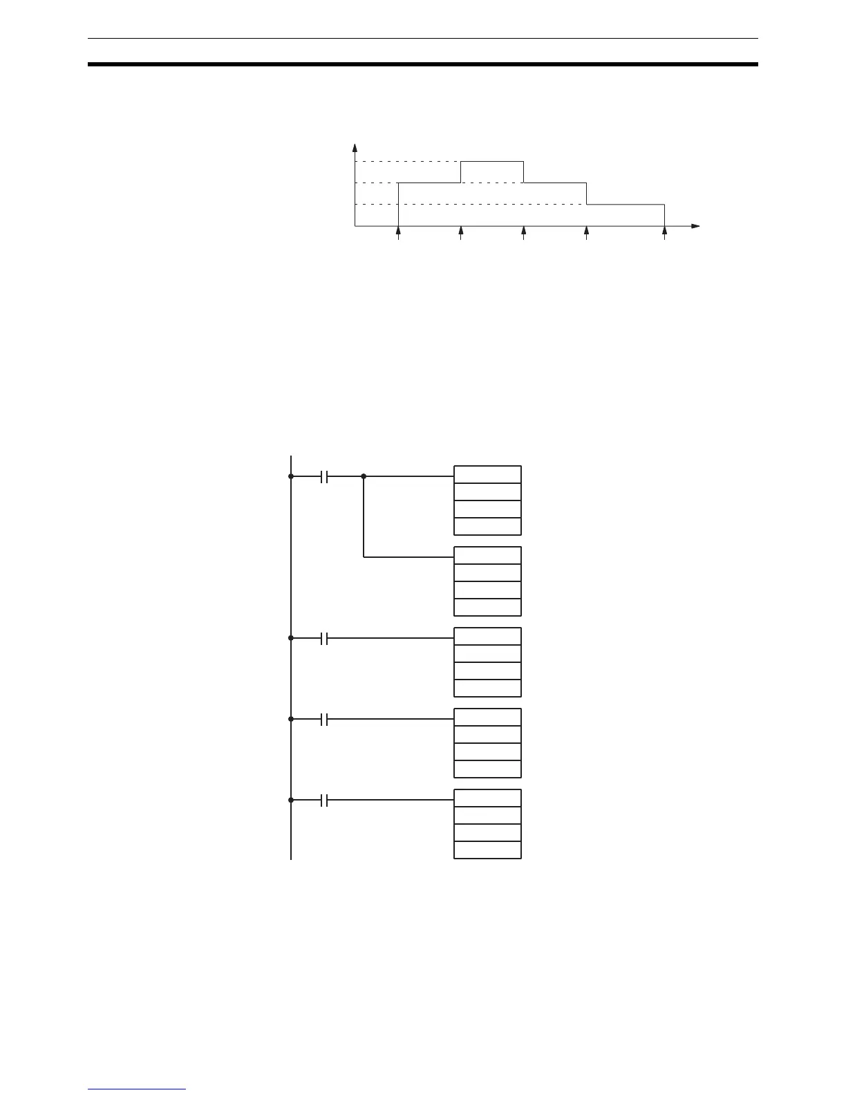
The following diagram shows the frequency of pulse outputs from port 1 as
the program is executed.
!Caution Be sure that the pulse frequency is within the motor’s self-starting frequency
range when starting and stopping the motor.
Note Speed control timing will be very accurate when frequency changes are per-
formed as input interrupt processes.
Example 2: Stopping
Pulse Output with
SPED(64)
The following example shows PULS(65) and SPED(64) used to control a
pulse output from port 1. The frequency is changed by executions of
SPED(64) with different frequency settings and finally stopped with a fre-
quency setting of 0.
Frequency
Time
1.5 kHz
1.0 kHz
0.5 kHz
05000
goes ON
00000
goes ON
00001
goes ON
00002
goes ON
10,000
pulses
@PULS(65)
004
001
05000
000
@SPED(64)
001
001
#0100
00005
@SPED(64)
001
001
#0150
00006
@SPED(64)
001
001
#0100
00007
@SPED(64)
001
001
#0000
When 05000 goes ON, PULS(65) sets port 1 for CW pulse
output. There is no number of pulses setting.
Starts pulse output from port 1 at 1 kHz in continuous mode.
When 00005 goes ON, the frequency from port 1 is
changed to 1.5 kHz.
When 00006 goes ON, the frequency from port 1 is
changed to 1 kHz.
When 00007 goes ON, the pulse output from port 1 is
stopped with a frequency setting of 0 Hz.
 Loading...


