475
Memory Areas Appendix C
Note 1. IR and LR bits that are not used for their allocated functions can be used as work bits.
2. The contents of the HR area, LR area, Counter area, and read/write DM area are backed up by a
capacitor. At 25
°C, the capacitor will back up memory for 20 days. Refer to 2-1-2 Characteristics in
the SRM1 Master Control Unit Operation Manual for a graph showing the backup time vs. tempera-
ture.
3. When accessing a PV, TC numbers are used as word data; when accessing Completion Flags, they
are used as bit data.
4. Data in DM 6144 to DM 6655 cannot be overwritten from the program, but they can be changed from
a Peripheral Device.
SR Area
These bits mainly serve as flags related to SRM1 operation or contain present and set values for various func-
tions. The functions of the SR area are explained in the following table.
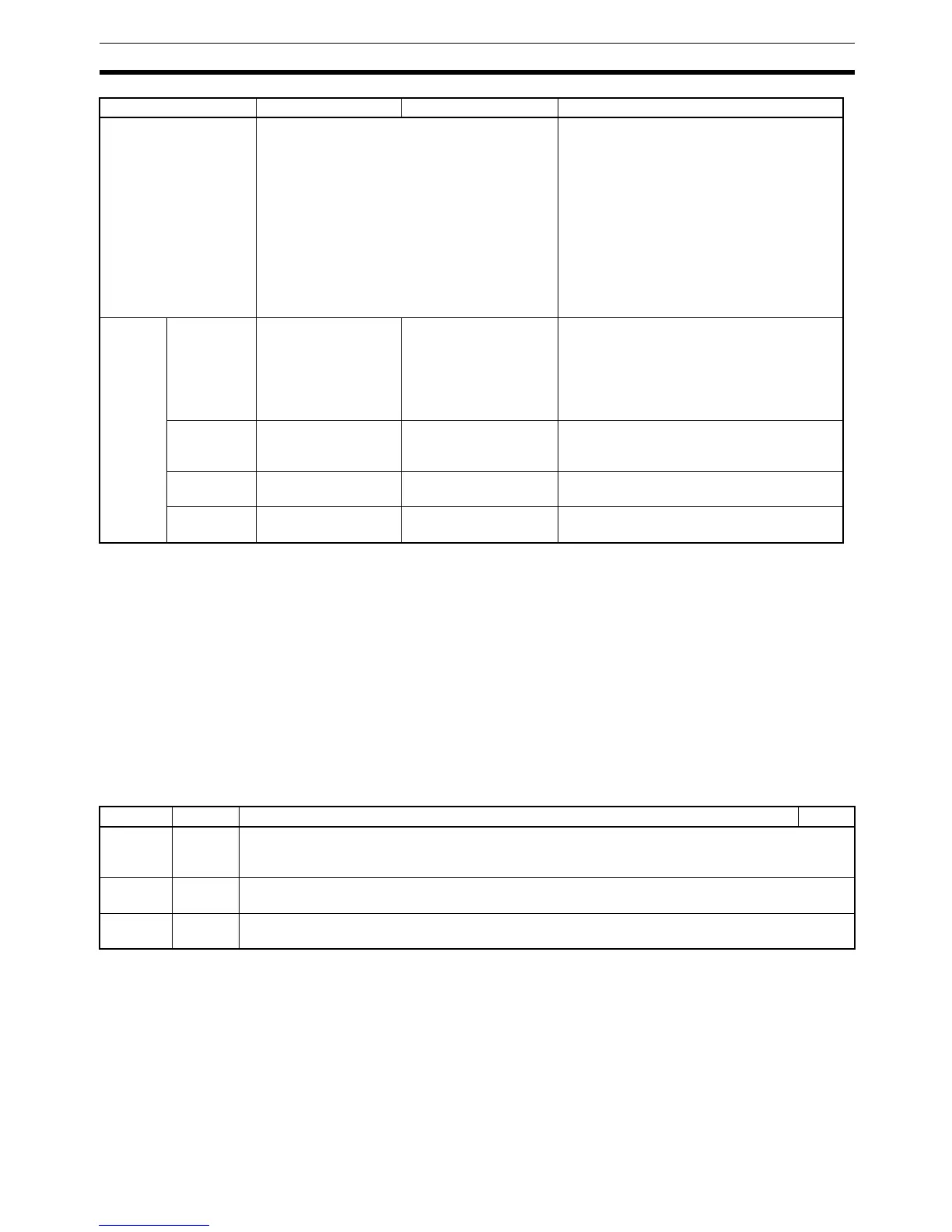
Timer/Counter area
2
TC 000 to TC 127 (timer/counter numbers)
3
Timers and counter use the TIM, TIMH(15),
CNT and CNTR(12) instructions. The same
numbers are used for both timers and
counters.
Timer/counter numbers should be specified
as bits when dealing with timer/counter
present values. The counter data will be
stored even when the SRM1 power is turned
off or operation is stopped or started.
When timer/counter are treated as up-flags
the number should be specified as relay
data.
DM area Read/write
2
DM 0000 to DM 1999
(2,000 words)
--- DM area data can be accessed in word units
only. Word values are retained when the
power is turned off, or operation started or
stopped.
Read/write areas can be read and written
freely within the program.
Error log
4
DM 2000 to DM 2021
(22 words)
--- Used to store the time of occurrence and
error code of errors that occur. Refer to 5-5
Coding Right-hand Instructions.
Read-only
4
DM 6144 to DM 6599
(456 words)
--- Cannot be overwritten from program.
PC Setup
4
DM 6600 to DM 6655
(56 words)
--- Used to store various parameters that con-
trol PC operation.
Data area Words Bits Function
Word(s) Bit(s) Function Page
SR 240
to
SR 247
00 to 15 Not used.
Can be used as work bits.
SR 248,
SR 249
00 to 15 Reserved.
SR 250,
SR 251
00 to 15 Not used.
Can be used as work bits.

 Loading...


