65
CQM1 Interrupt Functions Section 1-5
Note These words are refreshed only once every cycle, so there may be a differ-
ence from the actual PV.
Using the PRV(62) Instruction
Read the PV of an absolute high-speed counter by using the PRV(62) instruc-
tion. Specify absolute high-speed counter 1 or 2 in P (P=001 or 002).
The PV of the specified absolute high-speed counter is stored as shown
below.
The PV is read when the PRV(62) instruction is actually executed.
Reading Absolute
High-speed Counter
Status
The status of absolute high-speed counters 1 and 2 can be determined either
by reading the status of the relevant flags in the AR area or executing
PRV(62).
The following table shows the relevant AR area flags and their functions.
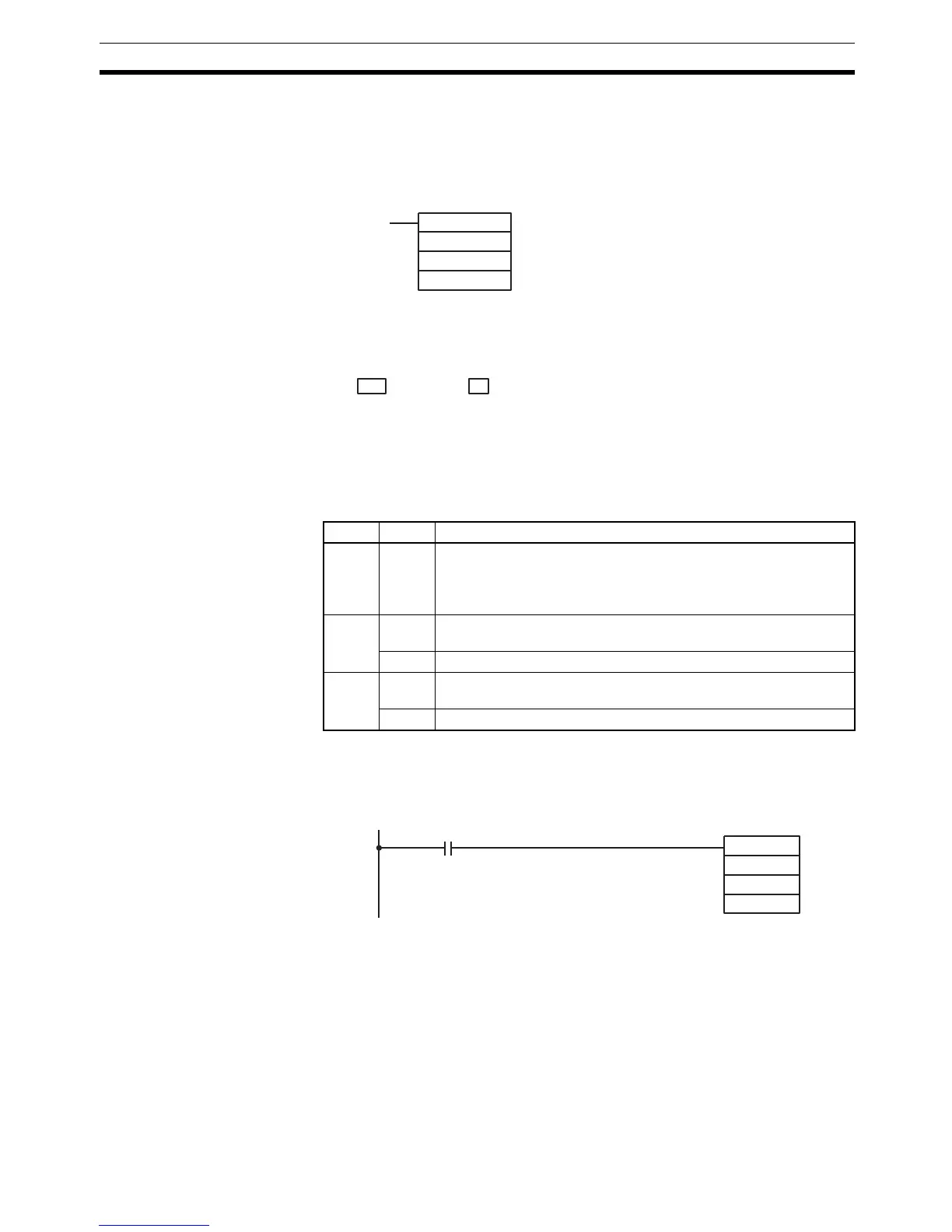
The comparison flag status of absolute high-speed counters 1 and 2 can also
be determined by executing PRV(62). Specify absolute high-speed counter 1
or 2 (P=001 to 002) and the destination word D. The flag status (0: Stopped;
1: Comparing) will be written to bit 00 of D. Bits 01 to 15 will be set to 0.
Operation Example This example shows a program that receives an input signal from an absolute
rotary encoder at port 1 and uses this input to control outputs IR 10000
through IR 10003. Absolute high-speed counter 1 is set for 8-bit resolution
and 360
° Mode, and range comparisons are used. Before executing the pro-
gram, set DM 6643 to 0100 (Port 1: 360
° Mode, 8-bit resolution).
Other PC Setup settings use the default settings. (Inputs are not refreshed at
the time of interrupt processing.)
In addition, the following data is stored for the comparison table:
(@)PRV(62)
P
000
P1
P: Port (001: port 1; 002: port 2)
P1: Leading word of PV
Leftmost 4 digits Rightmost 4 digits
D+1 D
BCD Mode 360˚ Mode
0000 0000 to 0000 4095 0000 0000 to 0000 0359
Word Bit(s) Function
AR 04 08 to
15
Indicates absolute high-speed counter status.
00: normal
01 or 02: Hardware error
03: PC Setup error
AR 05 00 to
07
Counter 1 Comparison Result flags for ranges 1 to 8.
(0: Not in range; 1: In range)
08 Counter 1 Comparison flag (0: Stopped; 1: Comparing)
AR 06 00 to
07
Counter 2 Comparison Result flags for ranges 1 to 8.
(0: Not in range; 1: In range)
08 Counter 2 Comparison flag (0: Stopped; 1: Comparing)
@PRV(62)
001
P
Execution condition
D