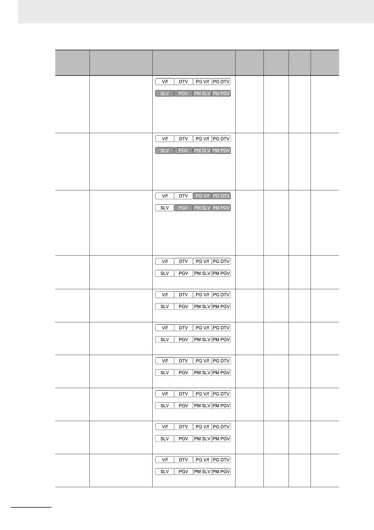
Parameter
No.
Function name Monitor or Data Range
Default
data
Setting
during
RUN
Unit Page
E146
2nd Overload Protect
Function Selection
0: Disable
1: Enable at constant speed
2: Enable during ACC/
constant speed operation
2
Availa-
ble
-
page
7-82
E147
2nd Overload Protect
Level
20 to 200 %
The data is interpreted as the
rated output current of the in-
verter for 100%.
180
Availa-
ble
%
page
7-82
E152
Starting Frequency
Selection at Frequen-
cy Pull-in Restart
0: Frequency at which the
power failure occurred
1: Maximum output frequency
2: Reference frequency
3: Starting frequency
3 - -
page
7-49
E154
RUN Time Over
(RNT)/Power ON T
ime
Over (ONT) Detection
Level
0 to 9999
0 -
10
hex
page
7-92
E157
Analog Input [AI1] De-
tection Upper Limit
Level
0 to 100 %
100
Availa-
ble
%
page
7-103
E158
Analog Input [AI1] De-
tection Lower Limit
Level
0 to 100 %
0
Availa-
ble
%
page
7-103
E159
Analog Input [AI1]
Level Detection Hyste-
resis Width
0 to 10 %
0
Availa-
ble
%
page
7-103
E160
Analog Input [AI2] De-
tection Upper Limit
Level
0 to 100 %
100
Availa-
ble
%
page
7-103
E161
Analog Input [AI2] De-
tection Lower Limit
Level
0 to 100 %
0
Availa-
ble
%
page
7-103
E162
Analog Input [AI2]
Level Detection Hyste-
resis Width
0 to 10 %
0
Availa-
ble
%
page
7-103
4 Parameter List
4-96
M1 Series Standard Type User's Manual (I669)
 Loading...


