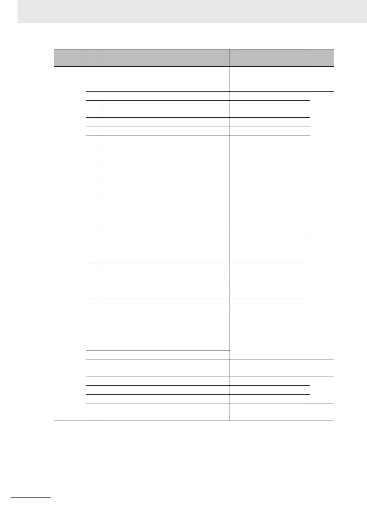
Parame-
ter No.
Da-
ta
Description Reference item Page
E20, E21,
E27
15 AX:
Switch MC on the input power
lines (for inverter input-side elec-
tromagnetic contactor)
Switch MC on the input power
lines
page
7-107
16 TU: Pattern operation stage transition Pattern operation
page
5-33
17 TO:
Pattern operation cycle complet-
ed
Pattern operation
18 STG1: Pattern operation stage 1 Pattern operation
19 STG2: Pattern operation stage 2 Pattern operation
20 STG4: Pattern operation stage 4 Pattern operation
21 FAR2: Frequency arrival signal 2 Frequency arrival signal
page
7-89
22 IOL2: Inverter output limiting with delay Inverter output limiting
page
7-106
25 FAN: Cooling fan in operation
Cooling FAN control method
selection
page
7-99
26 TRY: Auto-resetting Trip Retry Operation
page
7-58
27 Reserved -
page
7-155
28 OHF: Fin overheat warning Cooling fin overheat warning
page
7-102
29 SY: Synchronization completed
Simultaneous Start Synchron-
ized Run Operation
-
30 LIFE: Lifetime alarm Lifetime alarm (LIFE)
page
7-100
31 FDT2:
Over set frequency arrival signal
2
Frequency arrival signal
page
7-89
33 REFOFF: Reference loss detected Frequency Reference
page
5-29
35 RUN2: Inverter outputting Signal during run
page
5-68
36 OLP: Overload prevention controlling
Overload Limit/Overload
W
arning
page
7-82
37 OL2: Overload warning 2
38
OL: Overload warning
41 LOC: Light load detection signal Low current signal
page
7-102
42 OD: Excessive PID deviation PID Function
page
7-123
43 PID-CTL: Under PID control PID Function
44 PID-STP: Under sleep mode of PID control PID Function
46 OTQ: Overtorque Overtorque/undertorque
page
6-85
7 Other Functions
7-32
M1 Series Standard Type User's Manual (I669)

 Loading...


