6 - 23
6 Installation
NX-series EtherNet/IP Coupler Unit User’s Manual (W536)
6-1 Installing Units
6
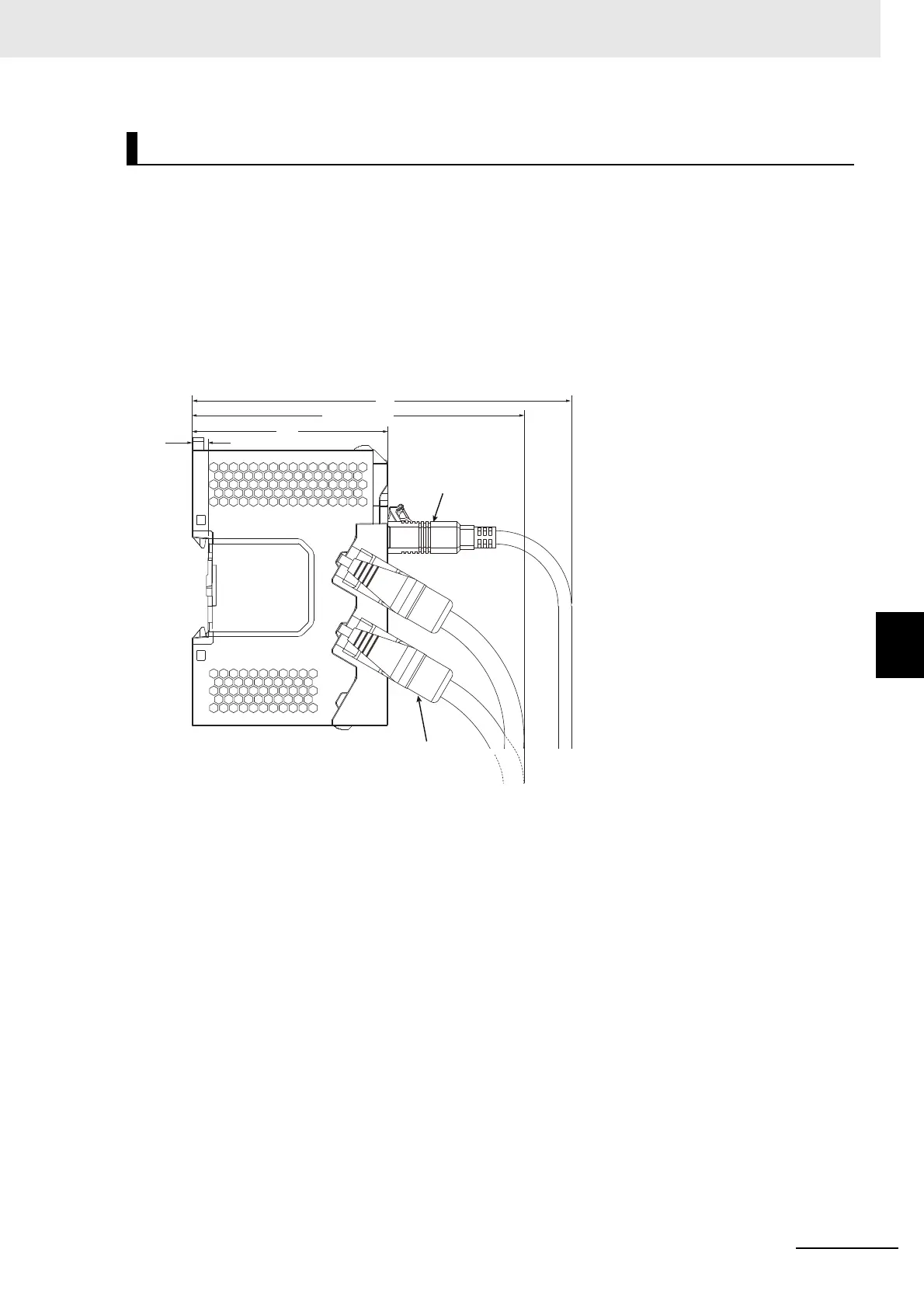
6-1-10 Assembled Appearance and Dimensions
The installation height of the EtherNet/IP Slave Terminal depends on the model of DIN Track and on the
models of NX Units that are mounted.
Also, additional space is required for the cables that are connected to the Unit. Allow sufficient depth in
the control panel and allow extra space when you mount the EtherNet/IP Slave Terminal.
The following figure shows the dimensions from the cables connected to the EtherNet/IP Coupler Unit
to the back of the Unit.
This is the installation height without the DIN Track of the EtherNet/IP Coupler Unit.
Refer to Installation Dimensions on page 6-21 for the influence on the installation height on the DIN
Track.
*1. This dimension depends on the specifications of the commercially available USB certified cable. Check the
specifications of the USB cable that is used.
*2. Dimension from Back of Unit to Communications Cables
• 100 mm: When an MPS588-C Connector is used.
• 120 mm: When an XS6G-T421-1 Connector is used.
As shown above, the installation height depends on the USB cable specifications when a USB cable is
used to connect the Support Software to the EtherNet/IP Coupler Unit. Check the specifications of the
USB cable that is used.
Refer to the manuals for the specific NX Units for the dimensions of NX Units.
Installation Height
USB cable
Communication cable
*1
71
5.8
100 to 120
*2