3 Specifications and Application Procedures
3 - 6
NX-series EtherNet/IP Coupler Unit User’s Manual (W536)
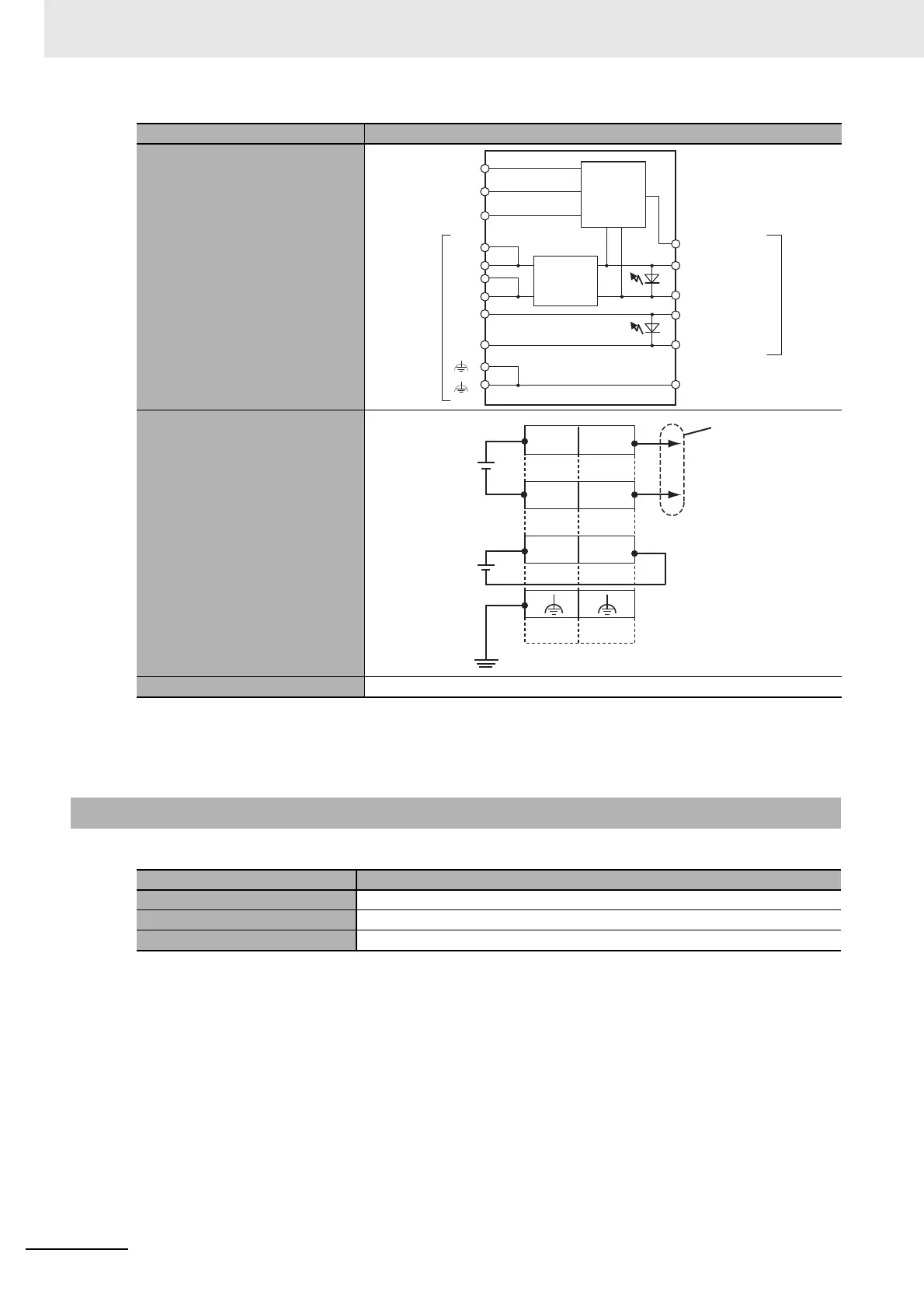
Circuit layout
Terminal arrangement
Accessory End Cover (NX-END01): 1
*1. Refer to the NX-series Safety Control Unit User’s Manual (Cat. No. Z930) for the number of Safety Control
Units that can be connected.
*2. Use a voltage that is appropriate for the I/O circuits of the NX Units and the connected external devices.
3-1-3 End Cover Specifications
Item Specification
Model NX-END01
Dimensions 12 × 100 × 71 (W×H×D)
Weight 35 g max.
Item Specification
NX Unit
power supply +
NX Unit
power supply −
Terminal
block
I/O power
supply +
I/O power
supply −
DIN Track contact plate
Peripheral
USB port
IN communications
connector
OUT communications
connector
NX bus
connector
UV
UV
UG
UG
IOV
IOG
UNIT PWR LED
I/O PWR LED
Internal
circuits
Non-isolated
power supply
circuits
IOV
UG
UV
IOG
UV
UG
A1
A8
B1
B8
Unit power supply
(24 VDC)
Through-wiring
for unwired
terminals.
I/O power supply
(5 to 24 VDC)
Ground to 100
Ω
or less.