7 - 11
7 Wiring
NX-series EtherNet/IP Coupler Unit User’s Manual (W536)
7-2 Connecting the Power Supply and Ground Wires
7
7-2-4 Precautions for Wiring the EtherNet/IP Slave Terminal
Together with Computers and other Peripheral Devices
This section describes how to connect wires to the screwless clamping terminal block on the Ether-
Net/IP Coupler Unit, the installation and removing methods, and functions for preventing incorrect
attachment.
You can connect ferrules that are attached to the twisted wires to the screwless clamping terminal
block. You can also connect the twisted wires or the solid wires to the screwless clamping terminal
block. If you connect the ferrules, all you need to do to connect the wires is to insert the ferrules into the
terminal holes.
7-2-4 Precautions for Wiring the EtherNet/IP Slave Terminal Together
with Computers and other Peripheral Devices
Caution
When you connect a computer or other peripheral device to the following Unit, either ground the 0-V
side of the external power supply (i.e. Unit power supply) or do not ground it at all.
• EtherNet/IP Coupler Unit with a non-isolated DC power supply (internal power supply cir-
cuits)
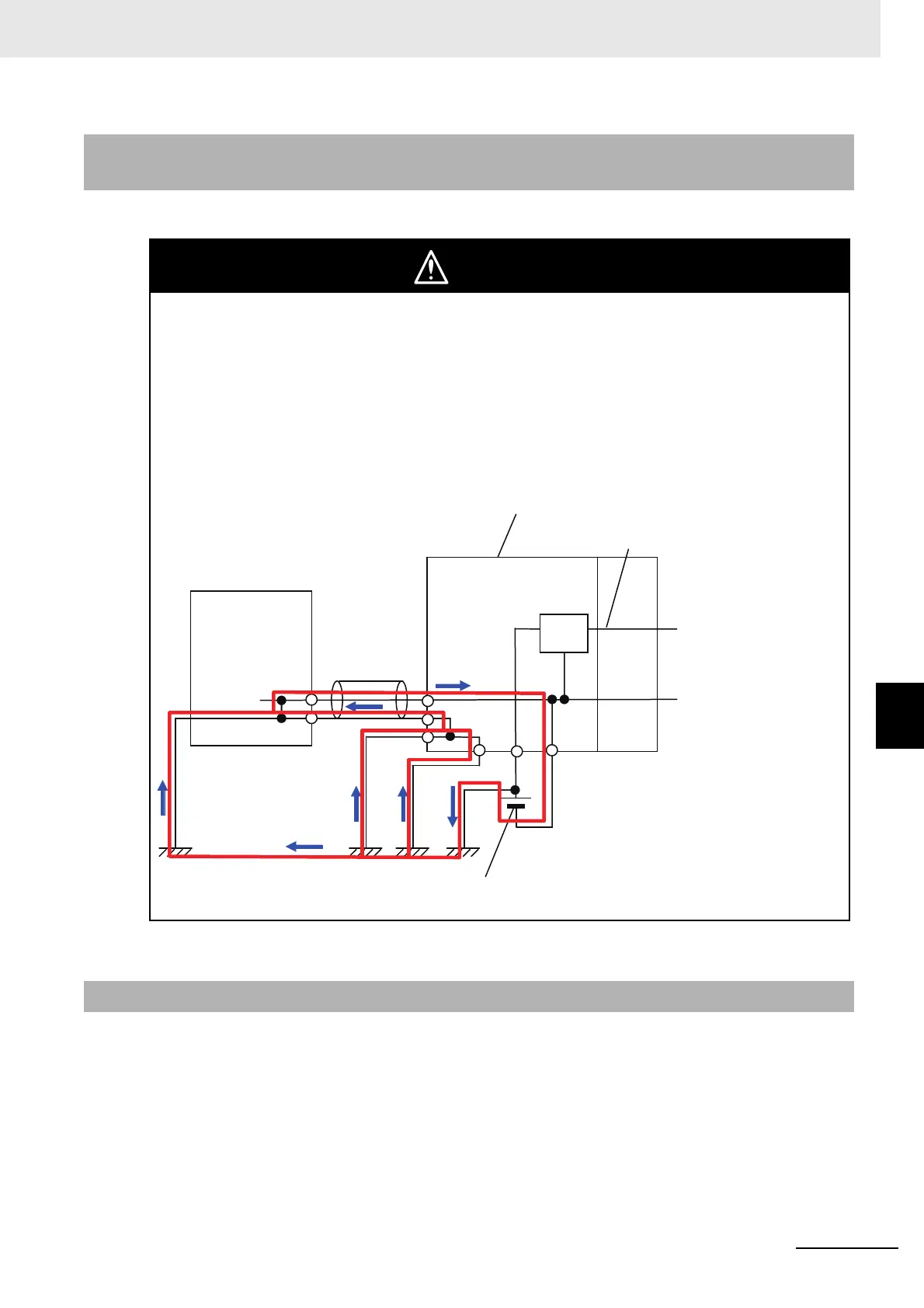
Depending on how the peripheral device is grounded, the external power supply (i.e. Unit power sup-
ply) may be shorted. Never ground the 24-V side of the power supply, as shown in the following fig-
ure.
Grounding That Causes a 24-V Power Supply to Short
7-2-5 Wiring to the Screwless Clamping Terminal Block
EtherNet/IP Coupler Unit
NX Unit power supply
Non-isolated DC power supply
(internal power supply circuit)
Unit power supply
Peripheral device
(e.g., computer)
Ground
terminal
Peripheral
device cable
24 V
0 V