9 Setting Up Slave Terminals
9 - 74
NX-series EtherNet/IP Coupler Unit User’s Manual (W536)
The I/O allocation display area includes the following information.
Padding is sometimes required in the I/O allocation to fill remaining bits within an incomplete byte of
data. This is done automatically to ensure whole bytes are used for data exchange.
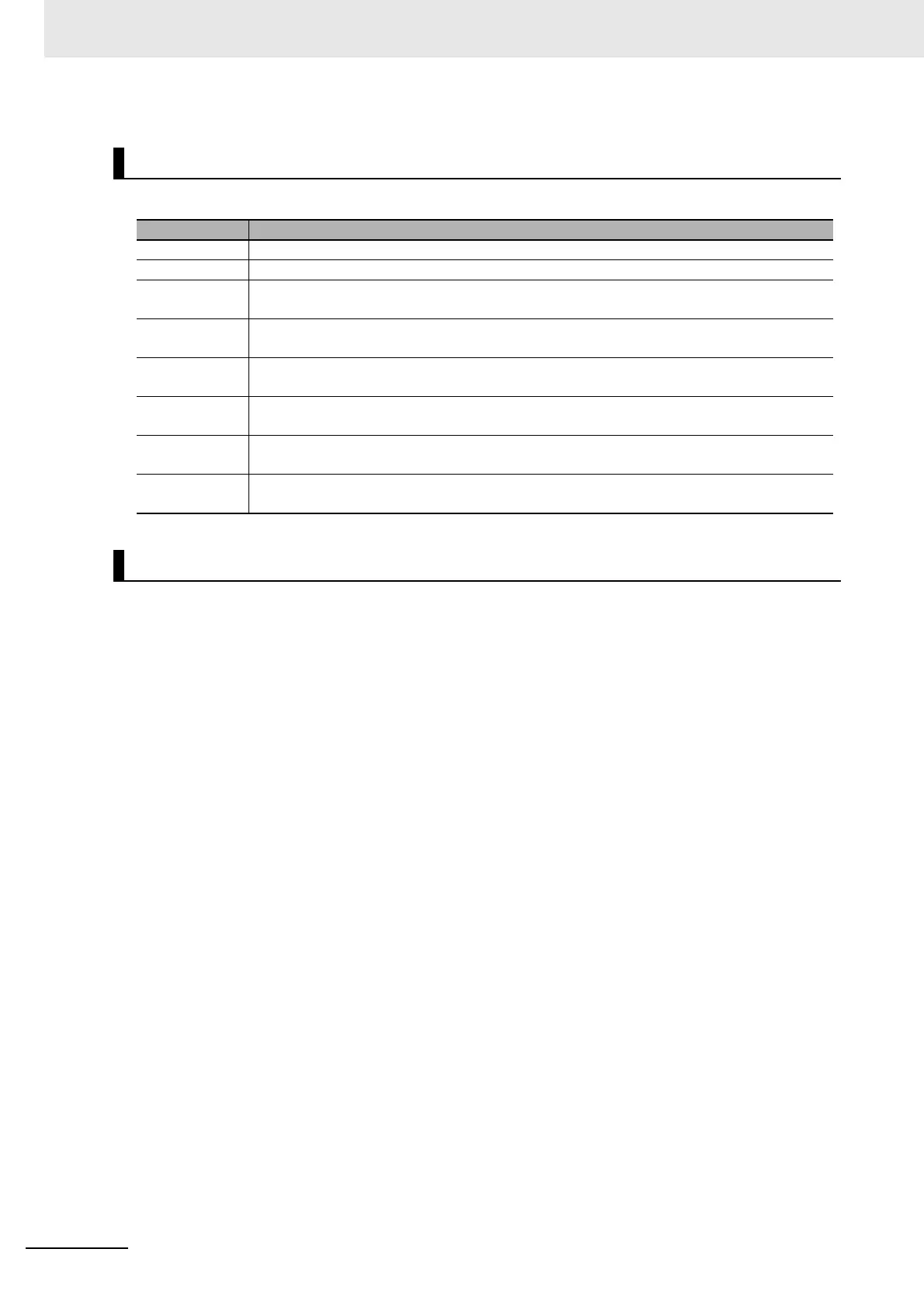
I/O Allocation Display
Item Description
Input Tab The overview of the input I/O allocation.
Output Tab The overview of the output I/O allocation.
Position The Slave Terminal Unit mounting location with corresponding Unit number. Refer to 9-6-1
Basic I/O Mapping on page 9-71 for more information.
Port I/O entries previously defined with the Edit I/O Allocation Settings button. Refer to 9-2-3 I/O
Allocation Information on page 9-12 for more information.
Bit Offset The consecutive order of bits assigned based on the size of each port accounting for any
necessary padding (see below for padding details).
Size Each item in the port area has a specific data size and this determines the bit offset and the
data input/output total size.
I/O Data Size The summary of the input/output bytes required to accommodate all port items previously
configured.
Output to File Clicking Output to File will generate a zip file that includes an .xsl and .xml file. Opening the
.xml file in a browser will display a table overview of the I/O allocation.
Padding