3-104
3-5 Servo Relay Units and Cable Specifications
3
Specifications
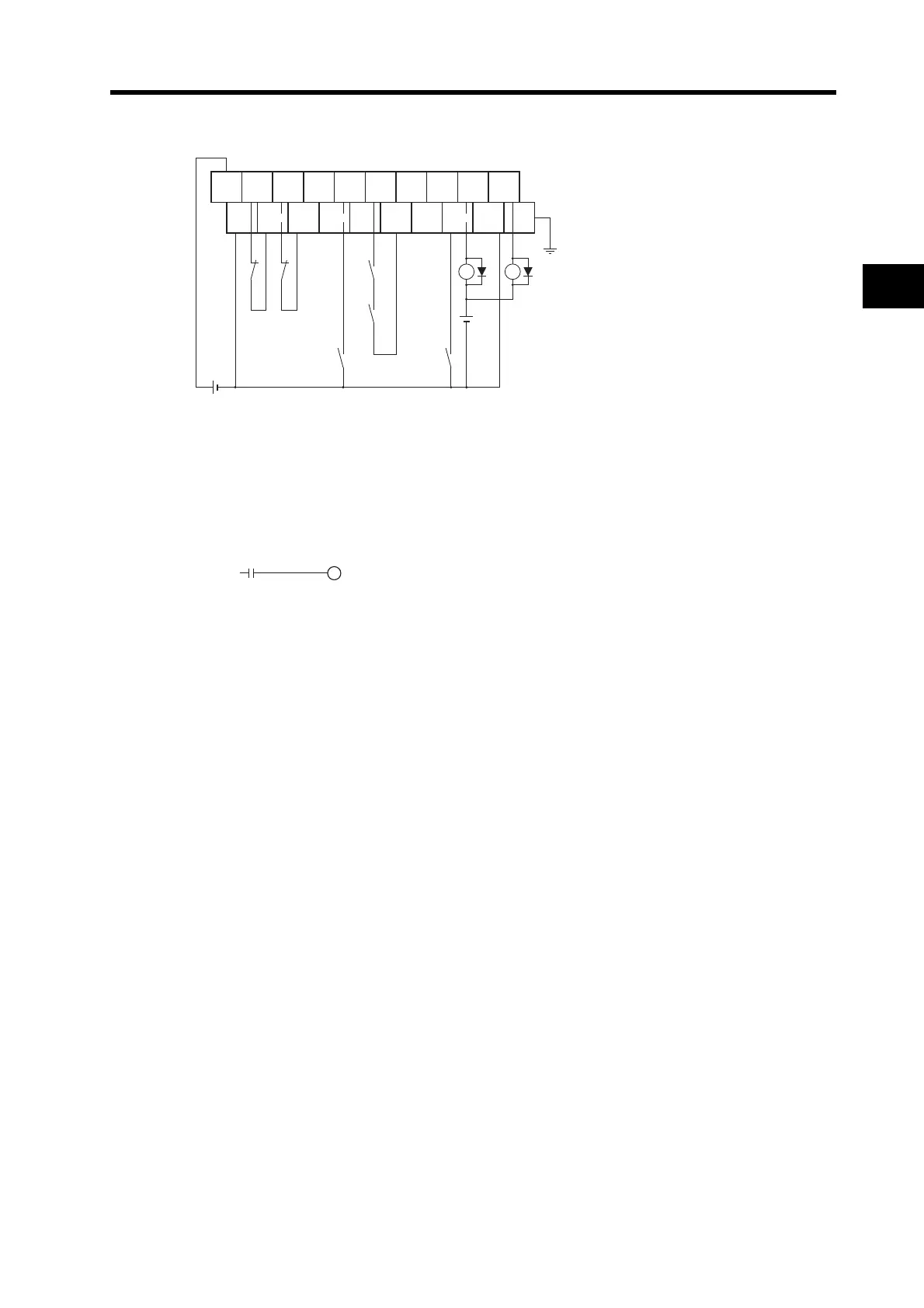
Wiring
The Servo Drive phase-Z output signal is wired to the origin proximity signal in this Terminal Block.
*1. CW and CCW limit input signals can also be input through Input Units. The bits for the CW/CCW
limit inputs in the CJ1M are as follows: CW: A540.08, CCW: A540.09 for pulse output 0 and CW:
A541.08, CCW: A541.09 for pulse output 1. For example, the flag for the CW limit input
(A540.08) can be controlled with an output from the ladder diagram using a bit allocated to the
actual input (CIO 2960.06) on the Input Unit, as shown below.
Example:
*2. The XB contacts are used to turn ON/OFF the electromagnetic brake.
*3. Connection to the MING input terminal is invalid.
*4. Do not connect unused terminals.
*5. The 0 V terminal is internally connected to the common terminals.
*6. The following crimp terminal is applicable: R1.25-3 (round with open end).
0 V
RUN ALM BKIR10
0
19
9
RESET ALMCOM
FG
24 VDC
X1 XB
24 VDC
X1
MINGIN6 IN7 IN8
IN9
(*2)
+24 V
Origin
proximity
Common Common Common Common Common
(*3)
CW limit (*1)
(CIO 2960.06)
CCW limit (*1)
(CIO 2960.07)
2960.06
A540.0

 Loading...

